


Special offers from our partners!

Find Replacement BBQ Parts for 20,308 Models. Repair your BBQ today.
16
107570
UNVENTED PROPANE/LP GAS FIREPLACE
For more information, visit www.desatech.com
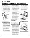
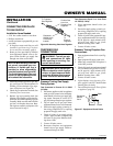
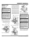
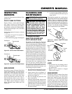
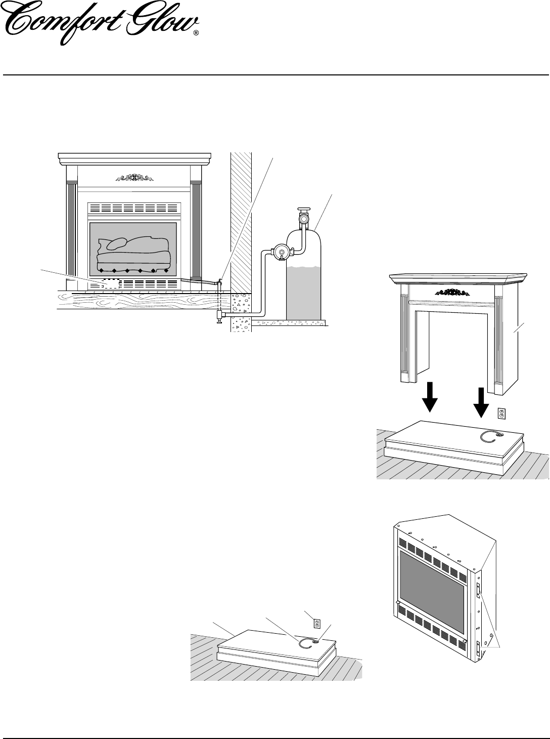
Figure 31 - Location of Nailing Flanges
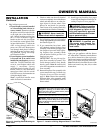
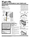
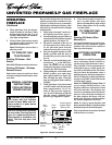
Figure 30 - Installing Cabinet Mantel
Cabinet
Mantel
3. If not already completed, install gas
piping to fireplace location. This instal-
lation includes an approved flexible gas
line (if allowed by local codes) after
the equipment shutoff valve. The flex-
ible gas line must be the last item in-
stalled on the gas piping. See Install-
ing Gas Piping to Fireplace Location,
page 14.
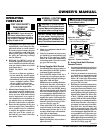
4. Place hearth base accessory against
wall at installation location. Cut an ac-
cess hole in hearth top to run flexible
gas line to fireplace (see Figure 29).
Make sure to locate access hole so cabi-
net mantel will cover it when installed.
Note:
You can secure base to floor us-
ing wood screws. Countersink screw
heads and putty over.
INSTALLATION
Continued
Nailing
Flanges
CONVENTIONAL FIREPLACE
INSTALLATION
Conventional installation of fireplace involves
installing fireplace along with corner, face, or
cabinet mantel with hearth base accessories
against a wall in your home. Follow instruc-
tions below to install fireplace in this manner.
Note:
The instructions below show installa-
tion using the cabinet mantel and hearth
base accessories (see Accessories, page 34).
The hearth base accessory shown is optional
for this installation. You can install fire-
place and cabinet mantel directly on the
floor. The corner mantel accessory cannot
be installed with the hearth bases. You must
install corner mantel directly on the floor.
1. Assemble cabinet mantel, hearth base,
and trim accessories. Assembly instruc-
tions are included with each accessory.
2. When installing blower, install a prop-
erly grounded, 120 volt three-prong
electrical outlet at fireplace location if
an outlet is not there. If possible, lo-
cate outlet so cabinet mantel will cover
it when installed (see Figure 29).
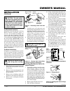
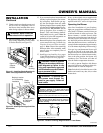
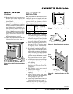
Figure 29 - Placing Hearth Base Accessory
Against Wall
Electrical
Outlet
Hearth
Base
Flexible
Gas Line
Gas Line
Access
Hole
5. Route flexible gas line through access
hole in hearth base.
6. Center cabinet mantel on hearth base
(see Figure 30). Make sure mantel is
flush against wall.
7. Break off nailing flanges (see Figure
31) with hammer or pliers.
8. Place cardboard or other protective ma-
terial on top of hearth base. Carefully
set fireplace on protective material, with
back of fireplace inside mantel opening.
9. Attach flexible gas line to fireplace gas
regulator. See Connecting Fireplace to
Gas Supply, page 15.
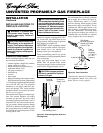
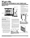
Figure 28 - Checking Gas Joints
Equipment Shutoff
Valve
Manual Gas
Valve
Propane/LP
Supply Tank