


Special offers from our partners!

Find Replacement BBQ Parts for 20,308 Models. Repair your BBQ today.
11
107570
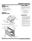
OWNER’S MANUAL
For more information, visit www.desatech.com
V
a
r
i
a
b
l
e
F
a
n
S
w
i
t
c
h
W
h
i
t
e
W
h
i
t
e
B
l
a
c
k
G
r
e
e
n
O
n
1
1
0
/
1
1
5
V
.
A
.
C
.
B
l
o
w
e
r
M
o
t
o
r
B
l
a
c
k
B
l
a
c
k
B
l
a
c
k
O
f
f
WARNING: Never touch the
blower wheel while in operation.
WARNING: Failure to position
the parts in accordance with sup-
plied diagrams or failure to use
only parts specifically approved
with this heater may result in dam-
age or personal injury.
WARNING: A qualified ser-
vice person must connect fire-
place to gas supply. Follow all
local codes.
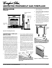
Operating the Blower
Light your gas appliance with the blower
off. After about 15 minutes, turn the blower
on to deliver heated air at the top louvers.
The blower features a variable control which
allows you to select the speed you desire.
Note:
Periodically check the louvers of the
firebox and remove any dust, dirt, or other
obstructions.
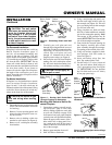
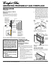
8. Plug in blower power cord.
a. If your fireplace system is installed
as a freestanding unit with an ac-
cessory mantel, determine whether
the power cord will exit the left side
or the right side of the firebox. In-
stall 1 plastic bushing provided into
the 1.5" hole in the floor support
bracket on the exit side (see Figure
16). Install the second plastic bush-
ing provided into the 1.5" hole in the
outer casing through which the
power cord will exit. Route power
cord through both plastic bushings
and plug the power cord into a prop-
erly grounded 3-prong wall recep-
tacle near the firebox.
b.If your fireplace system installation
is recessed and if an outlet is not
installed in your fireplace, you must
install the GA3555 Outlet kit with
cover in your fireplace which will
supply a convenient 3-prong
grounded electrical outlet for your
blower. Refer to the installation
manual provided with the model
GA3555 accessory for instructions on
wiring the duplex outlet.
Note:
A qualified installer must
make all electrical connections.
9. Check to make sure that all electrical
cords are completely clear of the blower
wheel and that there are no other for-
eign objects in blower wheel. Turn
blower on and check for operation.
Turn blower off by rotating knob fully
counterclockwise before continuing.
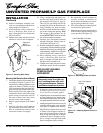
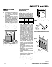
10. Peel off backing paper and stick supplied
wiring diagram decal near center of fire-
box bottom (Figure 17).
11. If gas connections have been made
and checked, replace fireplace floor
assembly. Feed flexible gas supply line
into fireplace base area while replac-
ing fireplace floor assembly. Make
sure the entire flexible gas line is in
fireplace base area.
IMPORTANT:
Do not pick up fire-
place floor assembly by burners. This
could damage burners. Only handle
base by grates.
Note:
Be careful of all
wires and components on underside of
floor assembly.
12. Reattach fireplace floor assembly with
screws removed in step 3 of Removing
Fireplace Screen and Floor Assembly,
page 8.
Note:
Discard the remaining
hardware items. After assembly, make
sure all wires are completely clear of
blower wheel.
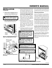
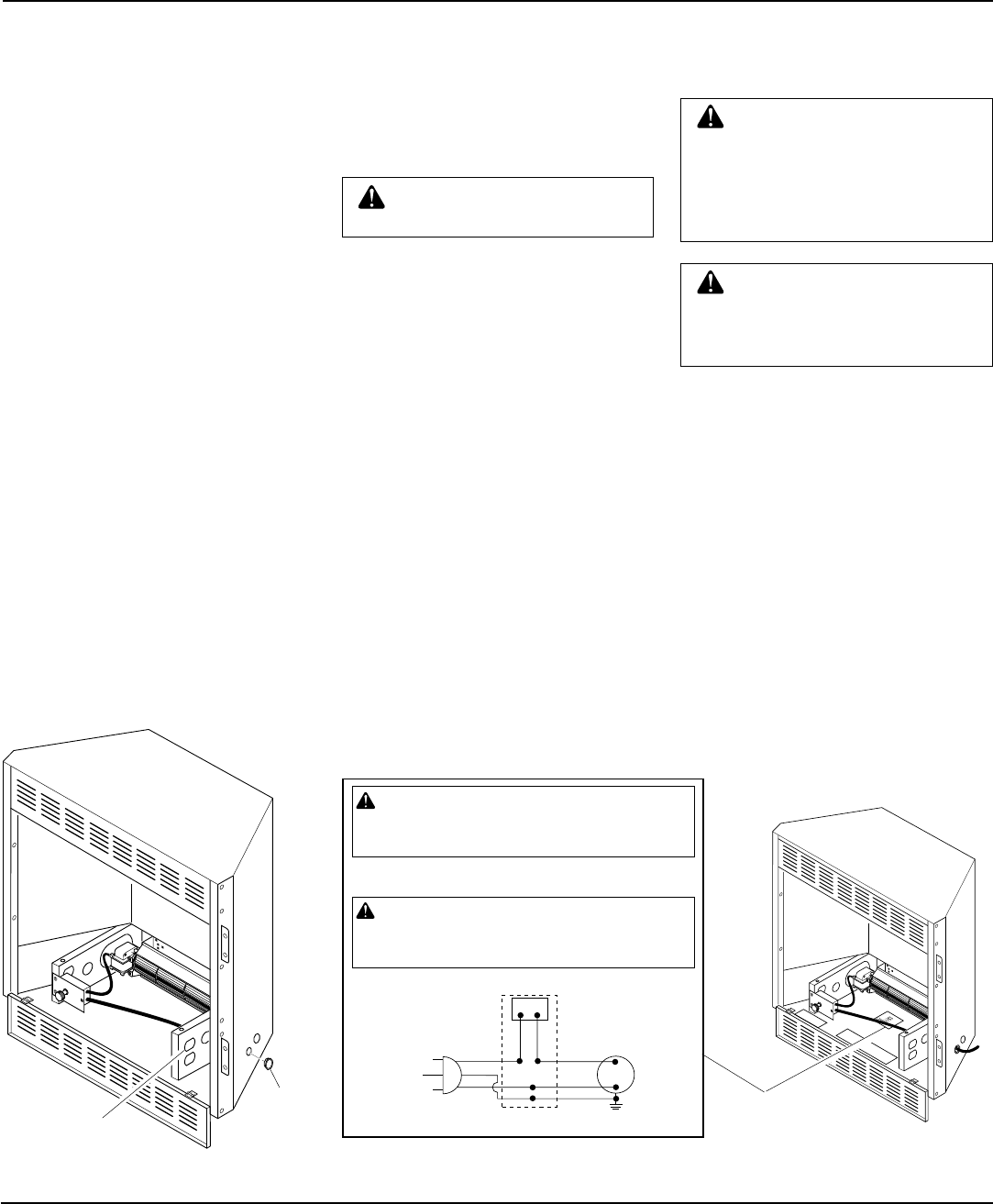
Figure 17 - Location of Wiring Diagram Decal 3" from Blower
Wiring
Diagram
101584-05
120 Vac. 60 Hz. . 78 Amps
DESA International, Bowling Green, KY
Variable
Fan Switch
WhiteWhite
Black
Green
On
110/115
V.A.C.
Blower
Motor
Black
Black
Black
Off
WARNING: Never attempt to service heater while it
is plugged in, operating, or hot. Burns and electrical
shock could result. Only a qualified service person
should service or repair heater.
If any of the original wire as supplied with the appliance must be
replaced, it must be replaced with 105°C wire or it’s equivalent.
WARNING: Label all wires prior to disconnection
when servicing controls. Wiring errors can cause im-
proper and dangerous operation. Verify proper opera-
tion after servicing.
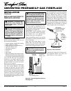
Figure 16 - Installing Plastic Bushing for
Power Cord
Plastic
Bushing
Right Floor
Support
Bracket
INSTALLATION
Continued
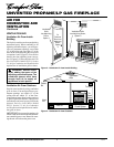
13. Install logs (see Installing Logs, pages
19 and 20) and fireplace screen (see In-
stalling Fireplace Screen, page 20).
Continued