


Special offers from our partners!

Find Replacement BBQ Parts for 20,308 Models. Repair your BBQ today.
15
107570
OWNER’S MANUAL
For more information, visit www.desatech.com
INSTALLATION
Continued
Continued
Installation Items Needed
• 5/16" hex socket wrench or nut-driver
• Phillips screwdriver
• sealant (resistant to propane/LP gas, not
provided)
1. If fireplace screen and floor are still
installed, see Removing Fireplace
Screen and Floor Assembly, page 8.
2. Route gas line (provided by installer)
from equipment shutoff valve to fire-
place. Route flexible gas supply line
through one of the access holes.
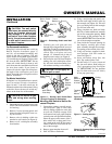
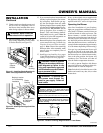
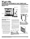
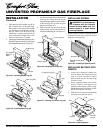
CONNECTING FIREPLACE
TO GAS SUPPLY
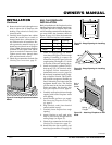
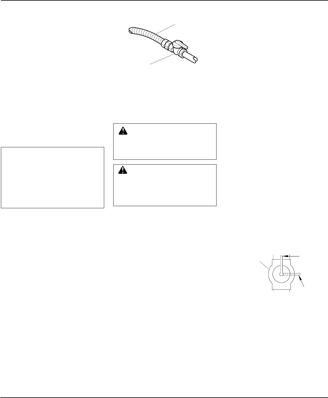
Figure 26 - Attaching Gas Lines Together
NOTICE: Most building codes do
not permit concealed gas con-
nections. A flexible gas line is
provided to allow accessibility
from the fireplace (see Figure 26).
The flexible gas supply line con-
nection to the equipment shutoff
valve should be accessible.
3. Attach the flexible gas line to gas sup-
ply (see Figure 26). Check tightness of
flexible gas line attached to gas regu-
lator of fireplace (see Figure 26).
4. Check all gas connections for leaks. See
Checking Gas Connections.
5. Replace log base assembly back into
fireplace. Feed flexible gas line into fire-
place base area while replacing log base
assembly. Make sure the entire flexible
gas line is in fireplace base area. Reat-
tach log base assembly to fireplace with
screws removed in step 2.
To
External
Regulator
Flexible Gas
Line from
Fireplace Gas
Regulator
To Fireplace
Gas Regulator
Equipment
Shutoff Valve
Provided by
Installer
➞
➞
Pressure Testing Gas Supply
Piping System
Test Pressures In Excess Of 1/2 PSIG
(3.5 kPa)
1. Disconnect appliance with its appliance
main gas valve (control valve) and equip-
ment shutoff valve from gas supply pip-
ing system. Pressures in excess of 1/2
psig will damage fireplace gas regulator.
2. Cap off open end of gas pipe where
equipment shutoff valve was connected.
3. Pressurize supply piping system by ei-
ther using compressed air or opening
propane/LP supply tank valve.
4. Check all joints of gas supply piping
system. Apply mixture of liquid soap
and water to gas joints. Bubbles form-
ing show a leak.
5. Correct all leaks at once.
6. Reconnect fireplace and equipment
shutoff valve to gas supply. Check re-
connected fittings for leaks.
CHECKING GAS
CONNECTIONS
WARNING: Test all gas pip-
ing and connections for leaks
after installing or servicing. Cor-
rect all leaks at once.
WARNING: Never use an open
flame to check for a leak. Apply a
mixture of liquid soap and water
to all joints. Bubbles forming show
a leak. Correct all leaks at once.
Test Pressures Equal To or Less Than
1/2 PSIG (3.5 kPa)
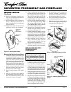
1. Close equipment shutoff valve (see
Figure 27).
2. Pressurize supply piping system by ei-
ther using compressed air or opening
propane/LP supply tank valve.
3. Check all joints from propane/LP sup-
ply to equipment shutoff valve (see Fig-
ure 28, page 16). Apply mixture of liq-
uid soap and water to gas joints.
Bubbles forming show a leak.
4. Correct all leaks at once.
Pressure Testing Fireplace Gas
Connections
1. Open equipment shutoff valve (see Fig-
ure 27).
2. Open propane/LP supply tank valve.
3. Make sure control knob of fireplace is
in the OFF position.
4. Check all joints from equipment shutoff
valve to thermostat gas valve (see Fig-
ure 28, page 16). Apply mixture of liq-
uid soap and water to gas joints.
Bubbles forming show a leak.
5. Correct all leaks at once.
6. Light fireplace (see Operating Fire-
place, pages 21 and 22). Check all other
internal joints for leaks.
7. Turn off fireplace (see To Turn Off Gas
to Appliance, page 22).
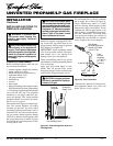
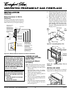
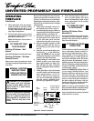
Figure 27 - Equipment Shutoff Valve
ON
POSITION
OFF
POSITION
Open
Equipment
Shutoff
Valve
Closed