


Special offers from our partners!

Find Replacement BBQ Parts for 20,308 Models. Repair your BBQ today.
9
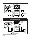
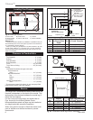
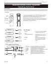
Chateau™
20011956
Control System
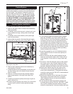
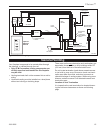
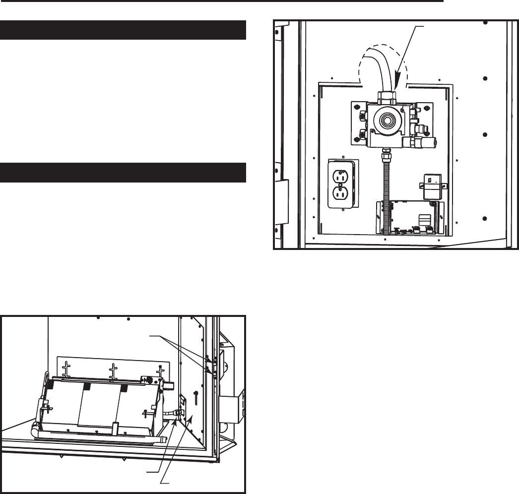
The gas control system is located on the right hand side
of the firebox behind an access panel and the decora-
tive brick panel. The fireplace is operated using only
the hand held remote control unit. The system wiring
diagram is shown in Figure 11. NOTE: If you choose
to install either the optional battery back-up mod-
ule, (Model DVTBBK), or the optional wireless wall
mountable remote control, (Part #20012267), it is
easier to install these at the time of fireplace instal-
lation. Refer to Items #11 & #20 in the next section.
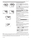
Control System Installation
1. Locate the fireplace in the desired location.
2. Remove the glass. Refer to Glass Frame Assembly
Removal section.
3. If installed, remove the lava rock, volcanic rock, and
-
irons, embers and logs, making note of each log’s
location.
4. If installed, remove the refractory brick panel right
side and rear pieces.
5.
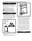
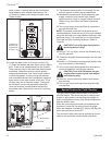
Using a back-up wrench, disconnect the gas supply
fitting near the right rear corner of the firebox. (Fig. 8)
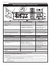
Gas Supply
Fitting
FP1794
Fig. 9 Connect gas supply to valve.
Gas Supply Fitting
FP1793
Fig. 8 Disconnect gas supply fitting and remove 13 screws
securing the cover plate.
Cover Plate
Pressure Test Ports
11.If you chose to install the optional back-up battery
pack (No. DVTBBK), you must install a wall box
within 15 feet (4.6 m) of the fireplace. Assemble the
connectors on one end of the supplied extension
wire harness to the mating connectors on the wire
harness within the control box. Make sure to connect
black coded wire to black and red coded wire to red.
12.The other end of the extension wire harness should
be connected to the wiring of the back-up battery
holder located within a wall box.
13.Insert the supplied four (4) “AA” batteries into the
battery holder. Be sure to note correct polarity for
each battery.
14.Mount electrical wall box containing back-up bat-
teries at a convenient location with 15 feet (4.6 m)
of the fireplace. Cover wall box using a blank wall
plate.
15.Connect a 120V AC electrical supply to the junction
box duplex outlet. Use a Romex-type strain relief
connector when running wires out through the box
knockout. Replace the duplex outlet and cover plate.
16.Plug the AC adaptor plug into the duplex outlet.
17.This control must now be programmed to the re-
mote control transmitter(s). To program the remote
control(s), make sure the 120V AC is connected and
powered to the fireplace.
18.Remove the battery door on the back of the hand
held remote control and install two (2) supplied
“AAA” batteries. Be sure to note correct polarity.
Replace battery door.
19.If you choose to install the optional wireless wall
mounted remote control (Part No. 20012267), install
two (2) button batteries provided with the remote
control by removing four (4) screws holding the back
6. Remove pilot assembly from burner assembly by
removing two (2) screws.
7. Carefully slide the burner assembly to the left out of
the way, taking care not to bend or break the pilot
tubes or wiring.
8. Remove 13 screws around the perimeter holding
large access panel on the right hand side of the
firebox.
9. Carefully pull back the panel just enough to gain ac
-
cess to control box.
10.Connect the gas supply to the valve. (Fig. 9) Be sure
to use a back-up wrench when tightening supply
fitting.