


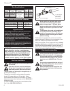
Special offers from our partners!

Find Replacement BBQ Parts for 20,308 Models. Repair your BBQ today.

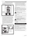
16
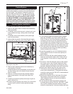
Chateau™
20011956
V
V
V
V
V
V
V
X
X
X
D
E
B
B
B
C
B
M
B
A
J
K
F
L
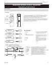
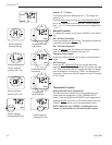
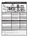
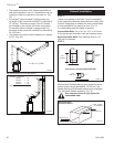
VENT TERMINATION AIR SUPPLY INLET
AREA WHERE TERMINAL IS NOT PERMITTED
H
I
V
B
CFM145a
DV Termin Location
5/01/01 Rev. 12/05/01
sta
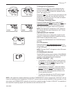
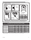
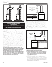
INSIDE
CORNER DETAIL
V
A
G
V
N
N
V
V
G
G
A
CFM145a
General Venting Information - Termination Location
A = Clearance above grade, veranda, porch, 12” (30 cm) 12” (30 cm)
deck, or balcony
B = Clearance to window or door that may be 6” (15 cm) for appliances 6” (15 cm) for appliances
opened < 10,000Btuh (3kW), 12” (30 cm) < 10,000 Btuh (3kW), 9”
for appliances > 10,000 Btuh (3kW) and (23 cm) for appliances > 10,000
< 100,000 Btuh (30kW), 36” (91 cm) Btuh (3kW) and < 50,000 Btuh
for appliances > 100,000 Btuh (30kW) (15kW), 12” (30cm) for
appliances > 50,000 Btuh (15kW)
C = Clearance to permanently closed window 12” (305 mm) recommended to 12” (305 mm) recommended to
prevent window condensation prevent window condensation
D = Vertical clearance to ventilated soffit located
above the terminal within a horizontal 18” (458 mm) for non-vinyl soffits 18” (458 mm)
for non-vinyl soffits
distance of 2 feet (610mm) from the center 24” (610 mm) for vinyl soffits 24” (610 mm) for vinyl soffits
line of the terminal
E = Clearance to unventilated soffit 24” (610 mm) 24” (610 mm)
F = Clearance to outside corner see next page see next page
G = Clearance to inside corner (see next page) see next page see next page
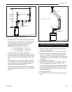
H = Clearance to each inside of center line 3’ (91 cm) within a height of 15’ 3’ (91 cm) within a height of 15’
extended above meter/regulator assembly above the meter/regulator assembly above the meter/regulator assy
I = Clearance to service regulator vent outlet 3’ (91 cm) 3’ (91 cm)
J = Clearance to nonmechanical air supply inlet 6” (15 cm) for appliances < 10,000 6” (15 cm) for appliances
to building or the combustion air inlet to any Btuh (3kW), 12” (30cm) for < 10,000 Btuh (3kW), 9”
other appliances appliances > 10,000 Btuh (3kW) and < (23 cm) for appliances > 10,000
100,000 Btuh (30kW), 36” (91 cm) Btuh (3kW) and < 50,000 Btuh
for appliances > 100,000 Btuh (30kW) (15kW), 12” (30 cm) for
appliances > 50,000 Btuh (15kW)
K* = Clearance to a mechanical air supply inlet 6’ (1.83 m) 3’ (91 cm) above if within 10’
(3m) horizontally
L = Clearance above paved sidewalk or paved 7’ (2.13 m)† 7’ (2.13 m)†
driveway located on public property
M = Clearance under veranda, porch, deck or 12” (30 cm)‡ 12” (30 cm)‡
balcony
N = Clearance above a roof shall extend a minimum of 24” (610 mm) above the highest point when it passes through the roof
surface, and any other obstruction within a horizontal distance of 18” (450 mm).
1 In accordance with the current CSA-B149 Installation Codes
2 In accordance with the current ANSI Z223.1/NFPA 54 National Fuel Gas Codes
* Clearance to a mechanical air supply refers to an HRV or other mechanical device that brings fresh air into the living space, not a fresh air for an
appliance combustion.
† A vent shall not terminate directly above a sidewalk or paved driveway which is located between two single family dwellings and serves both dwellings
‡ only permitted if veranda, porch, deck or balcony is fully open on a minimum 2 sides beneath the floor:
NOTE: 1. Local codes or regulations may require different clearances.
2. The special venting system used on Direct Vent Fireplaces are certified as part of the appliance, with clearances tested and approved by the
listing agency.
3. CFM Corporation assumes no responsibility for the improper performance of the appliance when the venting system does not
meet these requirements.
Canadian Installations
1
US Installations
2
Fig. 13 Vent termination clearances.