


Special offers from our partners!

Find Replacement BBQ Parts for 20,308 Models. Repair your BBQ today.
23
Chateau™
20011956
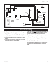
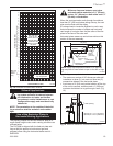
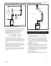
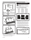
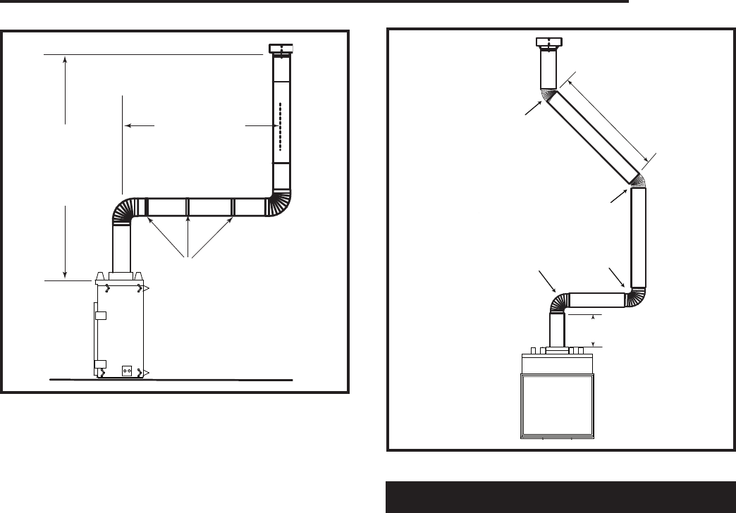
Max. 20' (6 m)
Max. Height
40' (12 m)
Min. Height
20' (6 m)
FP1244a
through the roof
max/min dims
4/03
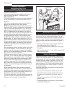
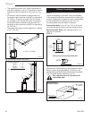
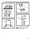
Pipe Straps Every 3’
(914mm)
FP1244a
Fig. 29 Support straps for horizontal runs.
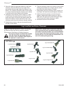
• Up to two (2) 30° or 45° elbows may be used within
the horizontal run. For each 30° or 45° elbow used
on the horizontal level the maximum horizontal
length must be reduced by 18” (457 mm).
Example: Maximum horizontal length
0 x 30° or 45° elbows = 10’ (3 m)
1 x 30° or 45° elbows = 8’6” (2.6 m)
2 x 30° or 45° elbows = 7’ (2.1 m)
• A minimum of an 12’ (3.7 m) vertical rise.
• Two sets of 30° or 45° elbows offsets within these
vertical installations. From 0 to a maximum of 8’ (2.4
m) of vent pipe can be used between elbows. (Fig.
30)
• SKCS8 must be used to support offsets. (Fig. 33)
This application will require that you first determine
the roof pitch and use the appropriate starter kit.
(Refer to Venting Components List)
•
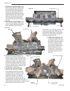
The minimum height of the vent above the highest
point of penetration through the roof is 2’ (610 mm).
(Fig. 34)
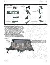
Vertical Through-the-Roof Installation
1
2
3
4
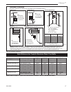
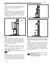
Max. 8' (2.4m)
FP1245a
through the roof
90 & 45 degree
FP1245a
Fig. 30 Typical offset application.
1 + 2 + 3 + 4 = 270°
Minimum 2’ (610mm)
Before Any Elbow
1. Locate your fireplace.
2. Plumb to center of the (8”) flue collar from ceiling
above and mark position.
3. Cut opening equal to 14
¹⁄₂” x 14¹⁄₂” (368 x 368 mm).
4. Proceed to plumb for additional openings through
the roof. In all cases, the opening must provide a
minimum of 1¹⁄₂” (38 mm) clearance to the vent pipe,
i.e., the hole must be at least 14¹⁄₂” x 14¹⁄₂” (368 mm
x 368 mm).
5. Place fireplace into position.
6. Place firestop(s) SKFS2A or Attic Insulation Shield
AIS-SK into position and secure. (Figs. 31, 32)
7. Install roof support (Fig. 33) and roof flashing making
sure upper flange of flashing is below the shingles.
8. Install appropriate pipe sections until the venting is
above the flashing.
9. Seal around the pipe.
10. Add additional vent lengths for proper height. (Fig.
34)