


Special offers from our partners!

Find Replacement BBQ Parts for 20,308 Models. Repair your BBQ today.
15
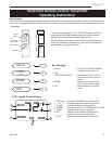
Chateau™
20011956
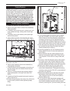
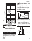
General Venting
Your fireplace is approved to be vented either through
the side wall, or vertical through the roof.
• Only CFM Corporation venting components spe-
cifically approved and labelled for this fireplace
may be used.
• Venting terminals shall not be recessed into a wall or
siding.
• Horizontal venting must be installed on a level plane
without an inclining or declining slope.
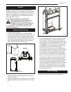
There must not be any obstruction such as bushes, gar-
den sheds, fences, decks or utility buildings within 24”
(610 mm) from the front of the termination hood.
Do not locate termination hood where excessive snow
or ice build up may occur. Be sure to check vent termi-
nation area after snow falls, and clear to prevent ac-
cidental blockage of venting system. When using snow
blowers, make sure snow is not directed towards vent
termination area.
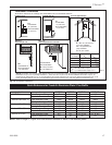
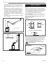
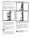
Location of Vent Termination
It is imperative the vent termination be located observ-
ing the minimum clearances as shown on following
page.
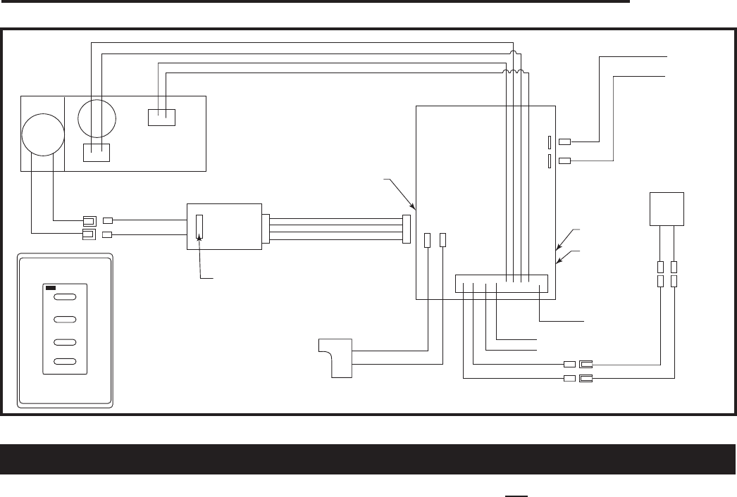
Pilot
Main
AF-4000
DC Motor
Red
Black
White or Green
Green or White
Orange or White
Black
Brown
Red
Orange
Main
Module
Black
Gnd
Brown
Brown
Black
Red
(SWI)
(SWI)
Extension Harness
FP1795
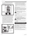
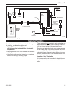
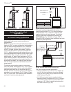
Chateau wiring diagram
3/07
White or Orange
S I
AC Adaptor
Power
Module
To Pilot Ignitor
To Pilot
Flame Sensor
Remote Battery
Back-Up Pack
Red
Black
Learn
Button
Remote/Off
Switch
Continuous
Pilot ON/OFF
Switch
(Optional
ON/OFF Switch)
Pulse/Continuous
Button
ON
OFF
HI
LO
Optional
Wireless
Remote
FP1795
Fig. 12 DVT38/44 wiring diagram.