


Special offers from our partners!

Find Replacement BBQ Parts for 20,308 Models. Repair your BBQ today.
6
Chateau™
20011956
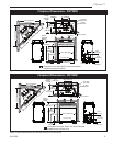
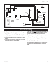
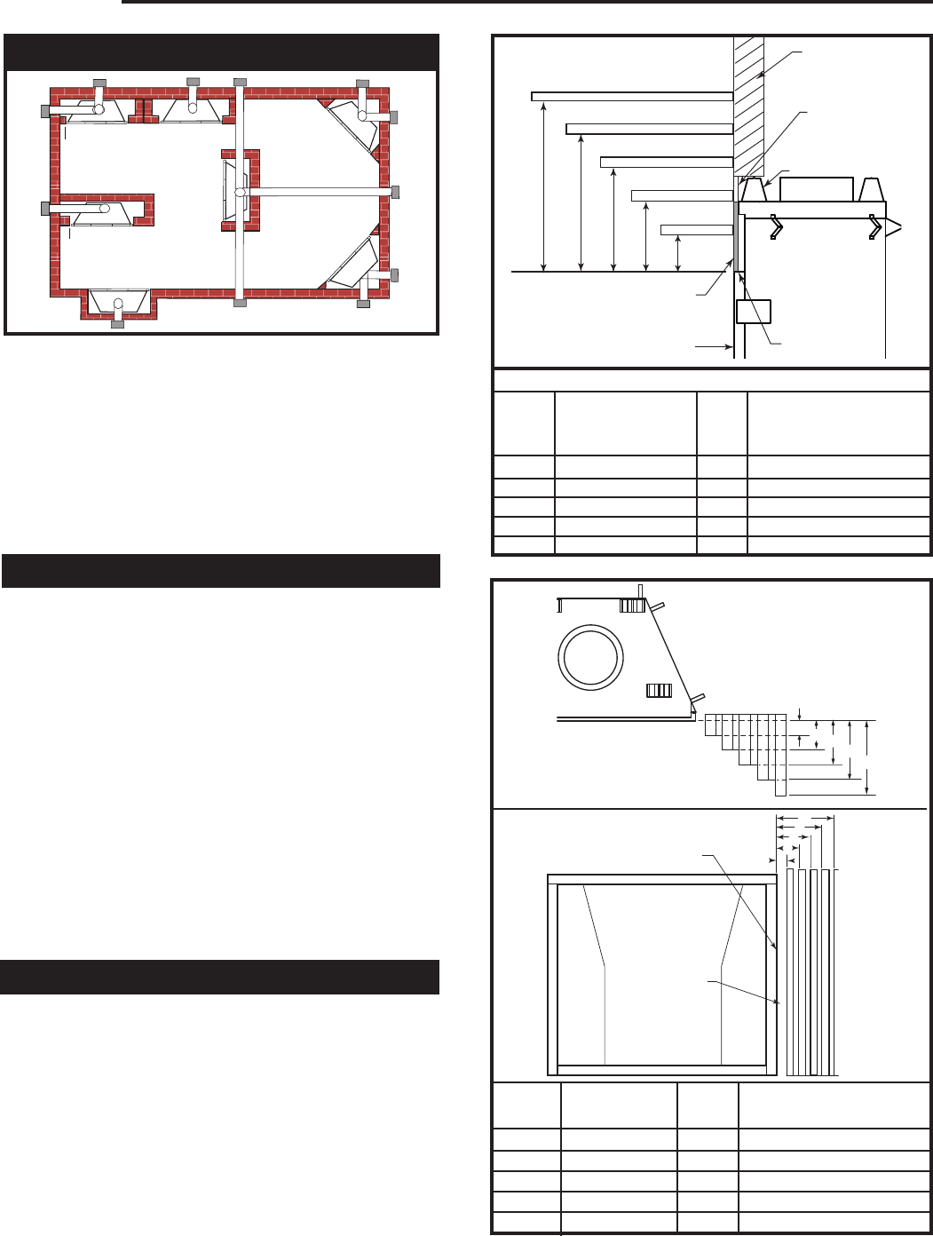
A) Flat on wall B) Cross corner C) **Island
D) *Room divider E) *Flat on wall corner F) Chase installation
Y) 6” minimum
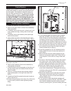
NOTE (Fig. 3):
** Island (C) and Room Divider (D) installation is possible as long as
the horizontal portion of the vent system (X) does not exceed 20’ (6
m). See details in Venting Section.
* When you install your gas fireplace in (D) Room divider or (E) Flat
on wall corner positions (Y), a minimum of 6” (152 mm) clearance
must be maintained from the perpendicular wall and the front side
edge of the fireplace.
Appliance
Top Standoffs ..................................................... 0” (0 mm)
Bottom* .............................................................. 0” (0 mm)
Side Standoffs ....................................................
0” (0 mm)
Back Standoffs ...................................................0” (0 mm)
Front
............................................................. 36” (914 mm)
Top of Unit to Ceiling ....................................36” (914 mm)
Venting
Horizontal Termination through-a-side wall:
Vertical Sections:
Sides ......................................................2¹⁄₂” (64 mm)
Horizontal Sections:
Top ......................................................... 3¹⁄₂” (89 mm)
Bottom ...................................................
1¹⁄₂” (38 mm)
Sides ......................................................2¹⁄₂” (64 mm)
Vertical Vent Application:
Sides .....................................................
1¹⁄₂” (38 mm)
* To prevent the potential for odors, do not use epoxy-filled
particle board directly under this fireplace.
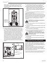
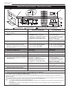
Mantels
The height that a combustible mantel is fitted above the
fireplace is dependent on the depth of the mantel. This
also applies to the distance between the mantel leg (if
fitted) and the fireplace.
For the correct mounting height and widths refer to
Figs. 4a and 4b, the following Mantel Charts.
Noncombustible mantels and legs may be installed at
any height and width around the appliance.
When using paint or lacquer to finish the mantel, such
paint or lacquer must be heat resistant to prevent
discoloration.
Clearance to Combustibles
Y
E
A
B
C
D
F
Y
B
X
LU584-1
Locating unit
2/4/99 djt
Locating Your Fireplace
Fig. 3 Locate gas fireplace.
LU584-1
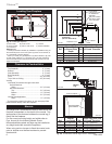
Fig. 4a Combustible mantel minimum installation.
A B C
D
E
V
W
X
Y
Z
CFM146c
DVT44
mantal chart
Mantel Chart
Mantel Shelf Mantel from Top
Ref. or Breast Plate Ref. of Comb. Chamber
Depth
V 10” (254 mm) A 10” (254 mm)
W 9” (229 mm) B 9” (229 mm)
X 8” (203 mm) C 8” (203 mm)
Y 7” (178 mm) D 7” (178 mm)
Z 6” (152 mm) E 6” (152 mm)
CFM146c
Combustible
Framing and Fin-
ish Wall Above
Standoffs
Standoff
Top of Sheet
Metal
Noncombustible Fin-
ish Material
(Such as Dura Rock)
Fireplace Front
May use combus-
tible facing mate-
rial in this area
J
F
G
H
I
CFM164b
Mantel Leg Char
DVT44
4/9/03 djt
Mantel
Leg
CFM164b
CFM170
DV Builder Front
View
O
N
M
L
K
CFM170a
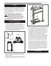
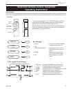
Fig. 4b Combustible mantel leg minimum installation.
Mantel Mantel Leg from Side
Ref. Leg Depth Ref. of Comb. Opening
F 12” (305 mm) K 12” (305 mm)
G 9” (229 mm) L 9” (229 mm)
H 6” (152 mm) M 6” (152 mm)
I 4” (102 mm) N 4” (102 mm)
J 3” (76 mm) O 3” (76 mm)
Side of Fireplace
Noncombustible
Finish Material