


Special offers from our partners!

Find Replacement BBQ Parts for 20,308 Models. Repair your BBQ today.
19
Chateau™
20011956
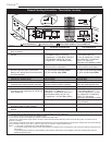
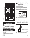
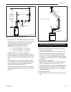
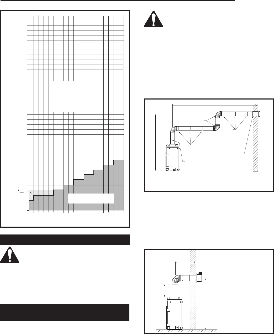
Sidewall Applications
Vertical Run (in feet)
(Measured from the appliance flue collar to the top of the vent pipe.)
Horizontal Run (in feet)
FP1359
DVT44
Horizontal
venting
graph
5/13/03 djt
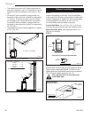
May use up to
three (3) 90°
elbows, but must
not have two (2)
consecutive 90°
elbows in horizon-
tal plane
Unacceptable vent-
ing configuration
FP1359
Fig. 16 Horizontal vent termination window.
May use
one (1)
elbow
only
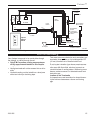
Since it is very important that the vent-
ing system maintain its balance between
the combustion air intake and the flue
gas exhaust, certain limitations as to vent
configurations apply and must be strictly
adhered to.
NOTE: The penetration to the outside of the build-
ing or structure shall be sealed air and weather
tight.
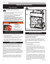
Use of the Restrictor Plates in
Horizontal Venting Applications
The primary purpose for the vent restrictor plate is to
regain flame height under certain venting conditions as
outlined below.
The DVT38IN is shipped with the fresh air plate set-
tings at #4 (this applies to both natural gas and
propane) when using the horizontal starter vent kit
SK8DVSK.
Minimum clearance between vent pipes
and combustible materials is 3¹⁄₂” (89 mm)
on top, 2¹⁄₂” (64 mm) on both sides and 1¹⁄₂”
(38 mm) on the bottom.
When the vent termination exits through foundations
less than 20” (508 mm) below siding outcrop, the vent
pipe must be flush with the siding.
It is always best to locate the fireplace in such a way
that minimizes the number of offsets and horizontal
vent length of vent pipe from the flue collar of the fire-
place to the face of the outer wall.
Horizontal plane means no vertical rise exists on this
portion of the vent assembly.
NOTE: Apply high temperature sealant or UL approved
high temperature metal adhesive tape as directed on Page
12.
FP1012
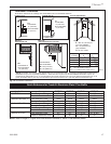
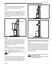
Top vent max run
1/25/00 djt
14’ (4.3m)
Pipe Straps
Every 3’ (914
mm)
Firestop/Zero
Clearance Sleeve
Pipe
Straps
Every 3’
(914 mm)
20’ (6 m)
FP1012a
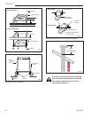
Fig. 17 Support straps for horizontal runs.
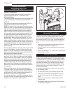
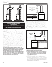
Minimum 2’ (610
mm) Section
Unitized Elbow
(SK890)
• The maximum number of 90° elbows per side wall
installation is three (3), but must not have two (2)
consecutive elbows in the horizontal plane.
• A minimum of 2’ (610 mm) vertical section off the top
of the unit is required, an elbow and a 1’ (305 mm)
maximum horizontal run to get through a wall. (Fig.
18)
2'
(610mm)
FP1237a
DVT44
horizontal plane
4/03
2'
(610mm)
C
L
X
FP1237a
Fig. 18 Minimum vertical run / maximum horizontal run.
Wall Opening
(DVT44) X = 7’3¹⁄₄” (2216 mm)
(DVT38) X = 6’9⁷⁄₈” (2080 mm)