


Special offers from our partners!

Find Replacement BBQ Parts for 20,308 Models. Repair your BBQ today.
IGE 300 Page 9 of 21
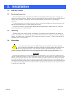
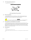
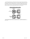
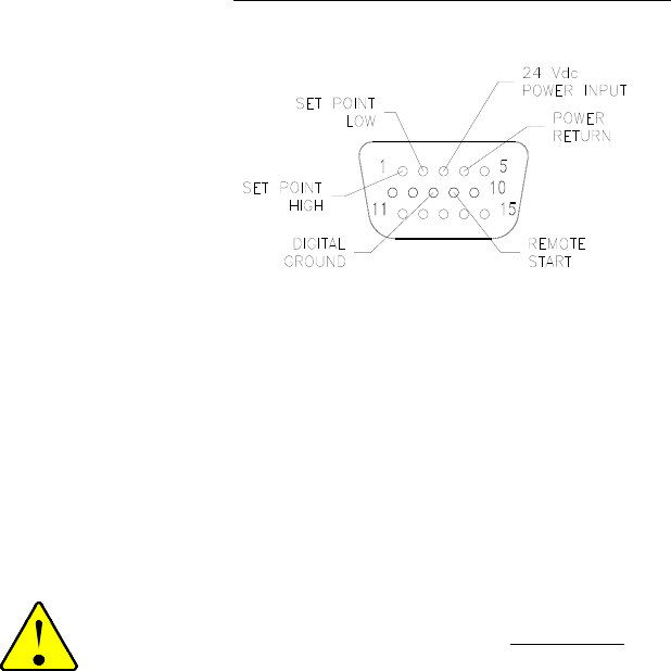
3.5. “D” Connector Electrical Pin outs
The figure below indicates all pin outs.
FIGURE 1- IGE-3000 “D” CONNECTOR
NOTE: Set Point High, Set Point Low and Remote
Start, use Digital ground Pin 8 as signal return path.
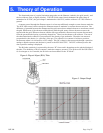
3.6. B/A Tube Installation
The Bayard/Alpert (B/A) tube may be installed in any orientation. Although the transducer tube is
rugged and will perform well in many harsh environments, the tube should be installed in a clean and
careful manner. The B/A tube is configured with the vacuum fitting requested.
CAUTION
The electronics unit is calibrated when married to the B/A tube. Avoid interchanging B/A
tubes with different electronics modules since this may affect accuracy and will void calibration.
3.7. Mounting B/A tube to IGE-3000 Electronics Module
The B/A tube plugs into the IGE-3000 via the 12 pin circular connector located inside the lower base
housing of the IGE-3000 electronics module. The B/A tube is keyed to ensure proper connections. Slightly
rotate the electronics unit until the keyway of the connector aligns with the key on the B/A tube, and then
snugly plug the electronics module to the B/A tube. Tighten the set screw located on the base housing to
the B/A tube. The set screw secures the tube to the electronics module and also ensures proper grounding
of the B/A tube to the IGE-3000 base housing.
3.8. Environmental:
Indoor use
Operating temperature range from 0° to 40° C
Maximum relative humidity: 80% for temperatures up to 31° C decreasing linearly to 50% Relative humidity at
40° C.