


Special offers from our partners!

Find Replacement BBQ Parts for 20,308 Models. Repair your BBQ today.
IGE 300 Page 14 of 21
5. Theory of Operation
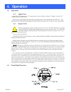
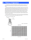
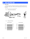
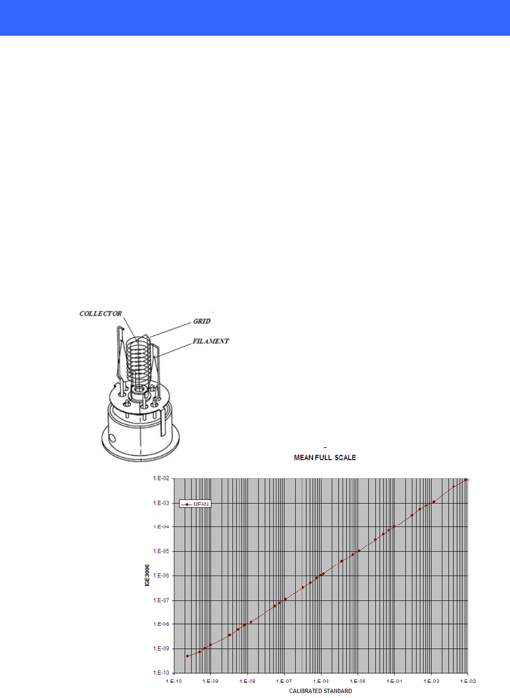
The functional parts of a typical ionization gauge tube are the filament (cathode), the grid (anode), and
the ion collector (refer to Figure 4 below). The IGE-3000 control circuit maintains the grid voltage is
maintained at 30 VDC, the grid voltage is maintained at 180 VDC, and the collector is 0 VDC relative to
ground.
A current passed through the filament causes it to heat up sufficiently enough to cause electron emission.
The IGE 3000 control circuit controls the filament current to maintain a constant electron emission. The
difference of potential between the filament and the grid causes these emitted electrons to accelerate toward
the grid. While most of the electrons collide directly with the grid, many of these electrons traverse the
region inside the grid. When an electron collides with a gas molecule, electrons may become disassociated
from the gas molecules leaving a positively charged ion. These ions accelerate to the collector. The rate of
the electron/molecule collisions is proportional to the density of gas molecules. Therefore ion current is
proportional to the density (i.e. pressure) of the gas. The collector’s ion current is fed into a precision
electrometer where it is converted to a DC voltage. This DC voltage is then processed through a precision
analog to digital converter and the data is passed to the IGE-3000 CPU. The CPU will then process this
data a pressure reading is displayed.
The B/A tube sensitivity is expressed by the term “K” factor and is dependant on the physical design of
the tube. The definition of K=ion current/ (emission current x pressure). The K factor for the IGE-3000 is
10 for nitrogen or air. If needed, the K factor can be modified via the “K Mode”.
Figure 4- Bayard Alpert (B/A) Tube
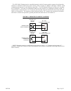
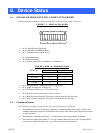
Figure 5- Output Graph