


Special offers from our partners!

Find Replacement BBQ Parts for 20,308 Models. Repair your BBQ today.

IGE 300 Page 12 of 21
4.3.3. DGas Mode:
CAUTION:
BEFORE INITIATING DEGAS, VACUUM MUST BE AT OR BELOW 1x10⁻⁷
EXCESSIVE DEGASSING AT ANY TIME CAN DISTORT THE GAUGE ELECTRODES AND
CAN RESULT IN A MISLEADING TRANSIENT DECREASE IN PRESSURE INDICATION
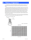
Degas mode is used to “Degas” or clean the inside areas of the BA tube of impurities. Degassing the
tube can improve readings and accuracy. Degassing is not effective at pressures above 1x 10
-7
. Degassing is
only recommended if the gauge is heavily contaminated or after exposure to surface active gasses such as
O
2
. As is typical of all B/A type gauges, pressure readings will be unstable for a several hours until the
chemical composition and absorbed layers on the newly cleaned surfaces in the BA tube reach equilibrium.
During Degas the emission current is increased to 10 mA and the grid voltage is raised to 500 VDC.
This action causes the temperature of the grid to be raised sufficiently enough to burn off most unwanted
contaminants.
4.3.4. (K-factor) Mode:
K factor mode is entered by scrolling to the K-factor position by slowly pressing the SELECT push
button. The K-factor can be set by turning the ADJUST encoder to the desired setting. The default
(normal) K factor for the IGE-3000 B/A tube is 10. If required the K factor can be adjusted from 1 to 99.
The K factor is associated with tube sensitivity and is a function of the physical tube design.
4.3.5. Fil (filament) Mode:
Fil mode is entered by scrolling to the Fil position by slowly pressing the SELECT push button. The
desired filament is then selected once in the Fil mode by turning the ADJUST encoder to the desired
setting. The IGE-3000 incorporates two separate identical filaments to dramatically increase B/A tube life.
Either filament can be selected at any time.
4.3.6. SP (set point) Mode:
SP mode is entered by scrolling to the SP position (HI or LOW) by slowly pressing the
SELECT push button. The set point values can then be selected by turning the ADJUST encoder to the
desired setting. SP alarms are indicated by the HIGH/ LOW LED’s on the status bar. In addition the IGE-
3000 has two corresponding TTL outputs (HI and LOW) for process control. These outputs are available
via the 15-pin connector. (Refer to Section 2.4/Figure 1).
To view the High set point, place the IGE-3000 in the High mode by slowly pressing the SELECT
button until the SP led and High led are flashing. The display then indicates the high set point value. To
change set point values rotate ADJUST CW to increase or CCW to decrease. There is no hysteresis (dead
band). During normal operation the alarm light will trigger and the TTL output (pin # 1) will go high
(+5V) if the pressure exceeds the set point.
Similarly, to view the Low set point, place the IGE-3000 in the Low mode by slowly pressing the
SELECT button again until the Low led and the SP led are flashing. The display then shows the low set
point value. To change set point values rotate ADJUST CW to increase or CCW to decrease. During
normal operation the alarm light will trigger and the TTL output (pin # 2) will go high (+5V) if the
pressure becomes less than the set point.
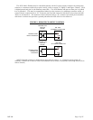
4.4. REMOTE FILAMENT CONTROL
Broad range pressure monitoring (i.e. atmosphere to 1X 10
-10
) can be realized when using the IGE-
3000’s Remote Control feature in conjunction with higher range gauges such as the Hastings HPM 2002,
Hastings HPM 2002 OBE, Hastings DV-6 CVT or similar instruments.
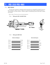
(Refer to Section 2.4/Figure 1 and Figure 3 below for wiring information).