


Special offers from our partners!

Find Replacement BBQ Parts for 20,308 Models. Repair your BBQ today.
14
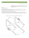
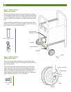
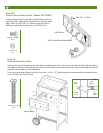
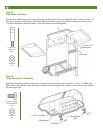
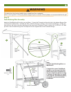
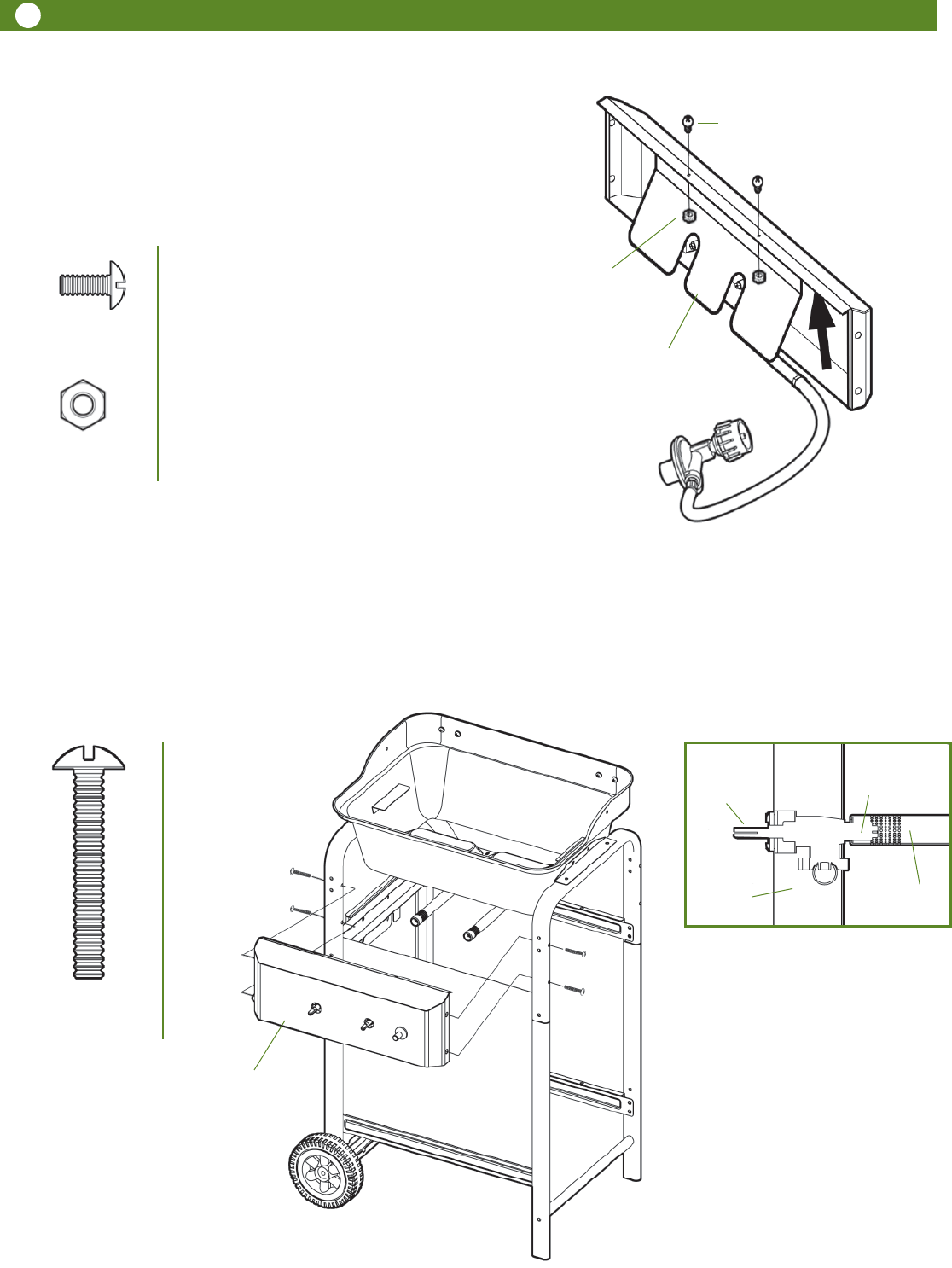
Step 13
Control Panel Assembly
Insert the Control Panel between the front legs and aligning the holes in the ends of the Control Panel with the holes in
the edges of the legs. Verify that the valve nozzles are inserted in the ends of the burner tubes (See Detail) and that the
regulator hose is over the Tank Side Brace.
From the outside edge of each front leg, insert two 1/4-20 x 1.97” Bolts through the leg tube and into threaded inserts
on the inside of the Control Panel.
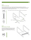
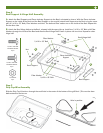
Detail
Burner
Tube
Valve
Nozzle
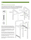
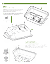
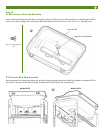
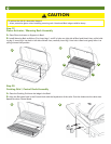
Step 12C
Control Panel Heat Shield - Model 6512 ONLY
Tuck top flange of 6512 Control Panel Heat Shield under the
top flange of the inside of the Control Panel so that the holes
align. Insert two 5/32-30 x .31” Bolts through the holes in
both parts and fasten in place with two 5/32-30 Nuts
5/32-30 Nut
5/32-30 x .31” Bolt
5/32-30 Nut
2 pc
6512 Control Panel Heat Shield
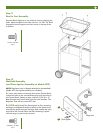
Control Panel
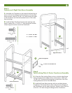
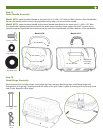
Valve
Stem
Control
Panel
5/32-30 x .31” Bolt
2 pcs
1/4-20 x 1.97” Bolt
4 pcs