


Special offers from our partners!

Find Replacement BBQ Parts for 20,308 Models. Repair your BBQ today.

GAS LINE AND ELECTRICAL INSTALLATION
GAS LINE AND ELECTRICAL INSTALLATION
17
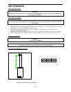
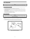
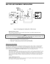
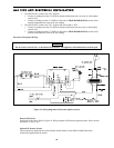
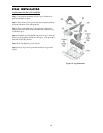
Figure 13: Wiring Diagram for Standing Pilot - Millivolt System
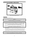
Optional DC Remote Systems
These instructions supersede the section entitled “Hearth Mount” in the Millivolt hand held remote
instructions supplied with the remote.
NOTE
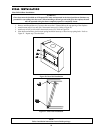
Remote receiver must be mounted outside the appliance, due to high temperatures inside the chamber. This
will prevent failures and longer battery life.
1. Plug in the remote connector wire to the remote receiver.
2. Mount remote control receiver at junction box (for your wall switch)
3. Connect the _” female connector to the valve TPTH and TH terminal.
Millivolt Control Valve Checklist:
The millivolt (thermopile) control is a self-powered combustion gas control. Refer to Figure 13: Wiring Diagram
for Standing Pilot - Millivolt System. The millivolt system and individual components may be checked with a
millivolt meter having 1-1000 mV range. Conduct each check listed below by connecting the meter test leads to the
terminals indicated. Refer to OPERATING INSTRUCTIONS for safety and lighting instructions.
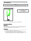
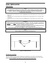
Thermopile Output Check
Pilot must be lit and the valve control knob turned to the “PILOT” or “ON” position. “RS-ON-OFF” switch
must be in the “OFF” position. Meter leads must be connected to the TP and the TH/TP terminals on the
control valve. If the meter reading is not 500-millivolt minimum, then readjust pilot for maximum millivolt
output. If millivolt reading is still below minimum specified, check wire connection and then replace the
thermopile.
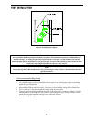
Complete Millivolt System Check
Pilot must be lit and the valve control knob turned to the “ON” position. Meter leads must be connected to
the TP and the TH/TP terminals on the control valve.