


Special offers from our partners!

Find Replacement BBQ Parts for 20,308 Models. Repair your BBQ today.
GAS LINE AND ELECTRICAL INSTALLATION
GAS LINE AND ELECTRICAL INSTALLATION
15
GAS LINE AND ELECTRICAL
Gas Line Installation:
NOTE
Plumbing connections should only be performed by a qualified, licensed plumber. Main gas supply must be
off when plumbing gas line to fireplace or performing service.
• Consult all codes. All gas piping must be installed to comply with local codes, or in the absence of local codes,
with the latest edition of the National Fuel Gas Code ANSI Z223.1.
• The appliance and its appliance main gas valve must be disconnected from the gas supply piping system during
any pressure testing of that system at test pressure in excess of 1/2 psi (3.5 kPa).
• The appliance must be isolated from the gas supply piping system by closing the equipment shutoff valve
during any pressure testing of the gas supply piping system at test pressures equal to or less than 1/2 psi (3.5
kPa).
• Use new black iron or steel pipe. Internally tinned copper or copper tubing can be used per National Fuel Gas
Code, section 2.6.3, providing gas meets sulfide limits, and where permitted by local codes.
• An ANSI approved manual shutoff valve must be installed immediately upstream of the gas supply connection
to the fireplace
• A sediment trap may be installed upstream of the fireplace to prevent moisture and contaminants from passing
through to the fireplace control and burner. Failure to do so could prevent appliance from operating reliably.
• On some local codes, the gas line must be connected to a gas shut-off valve recessed flush into the wall or floor
outside the fireplace. The valve should be controlled by a removable valve key for safety. In this case, remove
factory shut-off valve from the flex line and connect line direct to stub.
WARNING
Support the shut-off valve when attaching 1/2” gas line. Use a wrench to hold shut-off valve stationary.
Do not twist the flex line when tightening the 1/2” gas line.
WARNING
Connecting directly to an unregulated propane/L.P.G. tank can cause an explosion. An external regulator
must be used on all propane/LPG appliances to reduce the supply tank pressure to 13” w.c. (maximum).
WARNING
Do not connect directly to natural gas 1/2- psi or 2-psi systems. Always make sure the natural gas pressure is
regulated to 10.5 w.c. (maximum) before operating the unit.
• Check gas type. The gas supply must be the same as stated on the appliance’s rating decal. If the gas supply is
different from the fireplace, STOP! Do not install the appliance. Contact your dealer immediately.
• To ease installation, a 30” flex line with manual shut-off valve has been installed on this fireplace. Install 1/2”
gas line onto shut-off valve.
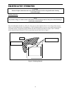
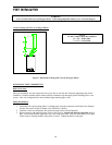
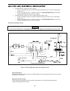
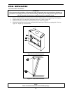
• Locate the gas line access hole in the outer casing of the fireplace. Remove the screw on the gas line cover
plate. Open the fireplace door, insert the gas supply line through the knock out hole on the gas line cover plate,
and connect it to the shut-off valve.
• After completing gas line connection, purge air from gas line and test all gas joints from the gas meter to the
fireplace for leaks. Use a soap and water solution or a gas sniffer.
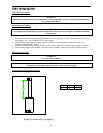
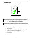
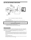
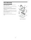
• To check gas pressure at valve, turn captured screw counter clockwise 2 or 3 turns and then place tubing to
pressure gauge over test point. Refer to Figure 12: Gas Pressure Check at Gas Valve. After taking pressure
reading, be sure and turn captured screw clockwise firmly to re-seal. Do not over torque. Check for gas leaks.
WARNING
Do not use open flame to check for gas leaks.