


Special offers from our partners!

Find Replacement BBQ Parts for 20,308 Models. Repair your BBQ today.
GAS LINE AND ELECTRICAL INSTALLATION
GAS LINE AND ELECTRICAL INSTALLATION
16
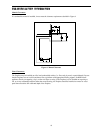
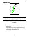
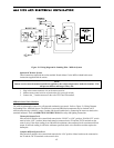
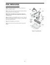
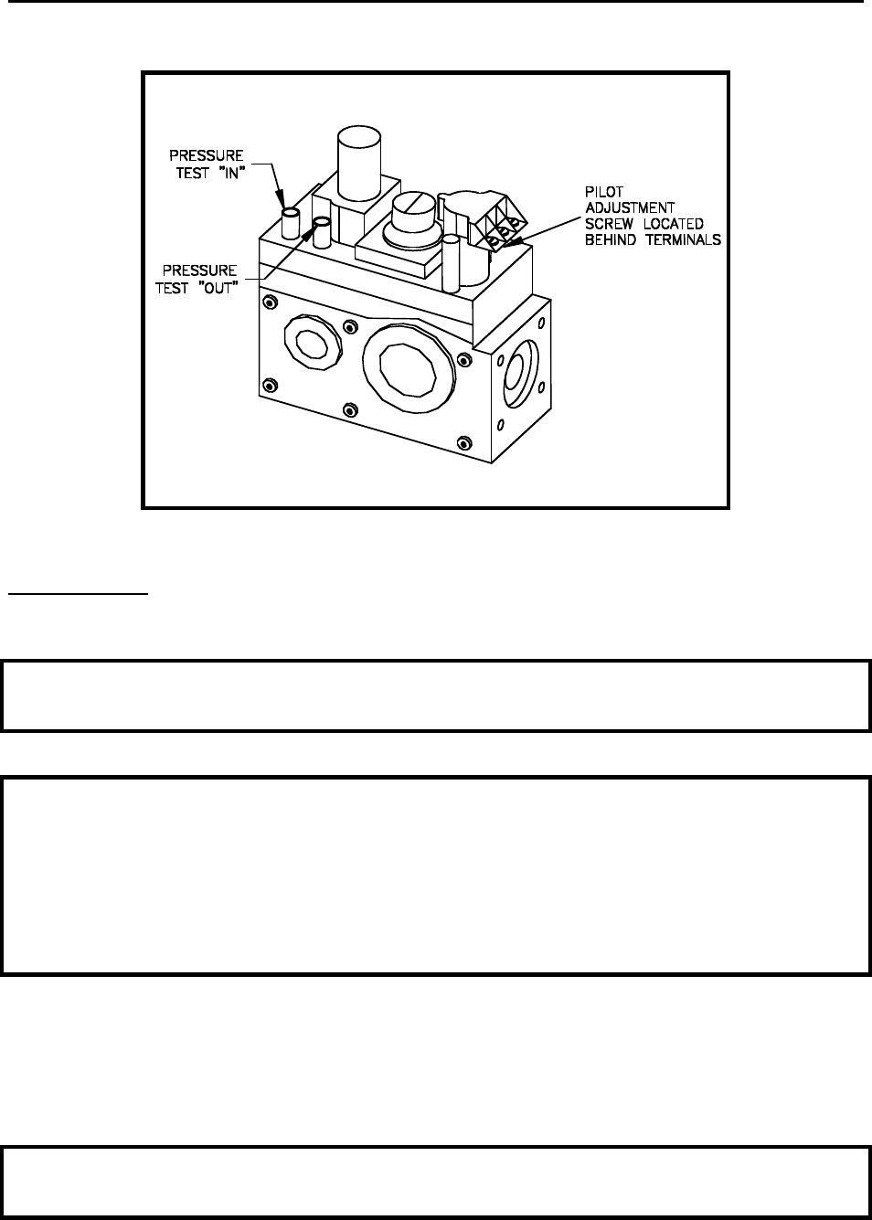
Figure 12: Gas Pressure Check at Gas Valve
Electrical Wiring:
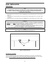
Standing Pilot Ignition Wiring-Millivolt Control:
WARNING
Do not connect 110-120 VAC to the Remote Wall Switch, DC Remote Control or the Millivolt Control Valve.
The appliance will malfunction or the valve will be damaged.
CAUTION
Electrical connections should only be performed by a qualified, licensed electrician. Main power must be off
when connecting to main electrical power supply or performing service. All wiring shall be in compliance
with all local, city, and state codes. The appliance, when installed, must be electrically grounded in
accordance with local codes, or in the absence of local codes, with the
National Electrical Code ANSI / NFPA 70 (latest edition), or the Canadian Electrical Code, CSA C22.1.
Label all wires prior to disconnection when servicing controls. Wiring errors can cause improper and
dangerous operations. Verify proper operation after servicing.
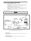
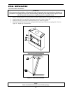
Remote Wall Switch
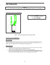
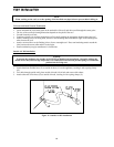
Fifteen (15) feet of 18 Ga. wire is provided as standard with this fireplace, that may be routed to a remote
wall switch. The wire has been pre-wired at the valve and routed through the right side, outer shell. (Access
is also available on the left side through the square hole on that side). Position the wall switch inside of a
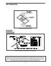
non-metallic junction box (not provided) at the desired location on the wall. Refer to Figure 13: Wiring
Diagram for Standing Pilot - Millivolt System. Do not extend beyond the wall switch wire length provided.
NOTE
Extended lengths of wire may cause the fireplace not to function properly. Longer length of wire is permitted
if the wire is a larger gauge (diameter) wire. Always check with local codes.