


Special offers from our partners!

Find Replacement BBQ Parts for 20,308 Models. Repair your BBQ today.

24
NOTE: DIAGRAMS & ILLUSTRATIONS ARE NOT TO SCALE.
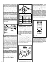
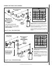
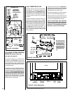
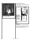
BLOWER CONTROL CIRCUIT WIRING
120V, 60HZ, 1PH
Factory Wired
Ground
Field Wired
Junction Box
Tab Intact
Tab
Broken
Plug blower
into this
receptacle
neerG - dnuorG
* Wall-mounted
ON/ OFF Blower
Switch or Variable
Speed Control Switch.
Blower
etihW - lar
t
ueN
120 VAC - Black
Green
Ground
Screw
White
Green
Neutral
Side of
Receptacle
Hot
Side of
Receptacle
Red
Black
Figure 38 - J-BOX WIRING
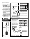
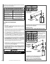
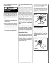
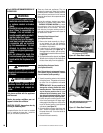
Step 6. CONNECTING GAS LINE
All codes require a shut-off valve mounted in
the supply line. The orientation of the shut-off
valve should face the front. Figure 39 illustrates
two methods for connecting the gas supply.
A Sediment Trap is recommended to prevent
moisture and debris in gas line from damaging
the valve.
The flex-line method is acceptable in the U.S.A.
where local codes permit, however, Canadian
requirements vary depending on locality. Instal-
lation must be in compliance with local codes.
These appliances are equipped with a gas flex-
line for use in connecting the unit to the gas line.
See Figure 39 for flex-line description. The
flex-line is rated for both natural and propane
gas. A manual shut off valve is also provided
with the flex-line.
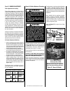
Step 5. WIRING - OPTIONAL FORCED AIR
BLOWER KIT (millivolt models only)
(See Figure 36 on Page 23)
An electrical outlet box is provided for the
installation of the LBLK-100 forced air blower
kit. Electrical power must be provided to this
box to operate these blowers. Install the blower
kit according to the installation instructions
provided with the kit.
If the blower kit is to be installed at the time of
installation or at a later date, the main power sup-
ply and wall switch must be installed at the time of
installation. This will require that the electrical
connections must be made BEFORE the fireplace
is framed and enclosed in the finished walls.
Route a 3-wire, 120 VAC, 60 Hz, 1 ph power
supply and connect to electrical receptacle wires
and wall switch or wall rheostat.
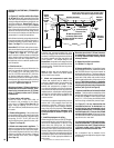
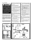
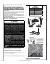
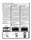
Gas Valve
Burner
ON/OFF Switch
Push Button
Piezo Igniter
Figure 40 - Control Compartment
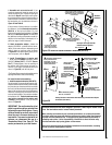
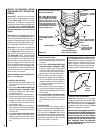
Glass Door
Gas Shut-
Off Valve
Gas Flex-
Line
Gas
Valve
3/8" NPT x
Flare Fitting
3/8" Flex Tubing
3/8" Nipple
3/8" Union
3/8" Close
Nipple
3/8" Shut-off Valve
1/2" x 3/8"
Reducer
Gas
Stub
1/2" x 3/8" Flare
Shut-off Valve
Gas Solid Line Connector
Gas Flex Line Connector
*Sediment
Trap
3"
Min
Figure 39 - GAS CONNECTION
If required, access the valve (see Figure 40 ) by
opening the lower control panel (see instruction
sheet provided with the facade kit for additional
information about the control panel).
The millivolt and electronic control valve has a
3/8" (10 mm) NPT thread gas supply inlet.
Bring the shutoff valve on the end of the flex-line
over to the hard pipe and tighten with wrenches
from above through the firebox opening.
Secure all joints tightly using appropriate
tools and sealing compounds (ensure propane
resistant compounds are used in propane ap-
plications). It is recommended to seal around
the gas line to prevent cold air leakage.
Note: The gas supply line
must be installed in accor-
dance with building codes
by a qualified installer
approved and/or licensed
as required by the locality.
In the Commonwealth of
Massachusetts, installation
must be performed by a
licensed plumber or gas
fitter.