


Special offers from our partners!

Find Replacement BBQ Parts for 20,308 Models. Repair your BBQ today.

22
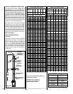
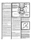
NOTE: DIAGRAMS & ILLUSTRATIONS ARE NOT TO SCALE.
D. Install Firestop / Spacers at ceilings and walls
- When Secure Flex penetrates a wall or ceiling,
a firestop / spacer is required: use the SF4.5 VF
firestop / spacer for ceilings and the SF4.5 HF
firestop / spacer for walls. See the appropriate
sections and Figures shown throughout the vent-
ing section for their installation requirements.
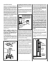
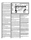
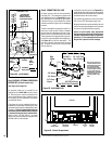
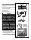
Note: Outer Pipe Is Pulled Away To Show
The Detail of The Inner Pipe
APPLY ONLY MIL-PAC BLACK
HIGH TEMPERATURE SEALANT
(Cat. No. 10K81) to the outside
surface of both collars of the
adaptor (be especially careful to
fill the grooves of the outer collar
to be covered by the flexible pipe)
and slide flexible pipe over inner
and outer adaptor collars.
1-3/4 inch (44 mm) Flexible
pipe and adaptor outer collar
overlap
Adaptor (SV4.5RF)
Attach adaptor to appliance
Collar, or secure vent sections
Flex Vent
Gear Clamps
Securing screw
- 3 places, 120° apart
(equally spaced) just
below gear clamp
1-3/4 in. (44 mm) Flexible
pipe and adaptor inner collar
overlap
Securing Screw - 3 places,
equally spaced, just below
gear clamp.
Figure 34
VERTICAL OR HORIZONTAL VENTING
USING KITS AND COM-
PONENTS
Secure Flex™ venting kits and components
may be used in any venting application in place
of rigid Secure Vent™ (SV4.5) direct-vent
components. All restrictions, clearances and
allowances that pertain to the rigid piping apply
to the flexible venting. Secure Flex kits may
not be modified; also, under no circumstances
may separate sections of flex pipe be joined
together.
Secure Flex kits may be added to the end of a
vent run made up of rigid Secure Vent (SV4.5)
vent sections provided that doing so does not
violate any of the venting length, height, routing,
horizontal to vertical ratio requirements or clear-
ance considerations detailed in this manual.
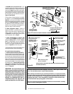
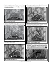
Secure Flex kits come with an adaptor that
can be fitted to the inclined channel end of
the last Secure Vent (SV4.5) vent section in a
rigid system in the exact same fashion as any
other Secure Vent section. Align the dimpled
end of the adaptor over the previously installed
section or appliance collar, adjusting the radial
alignment until the four locking dimples of the
adaptor are aligned with the inlets of the four
incline channels of the last vent section or collar.
Push on the adaptor until it fully engages, then
twist the adaptor clockwise running the dimples
down and along the incline channels until they
seat at the end of the channels.
Attach the flexible vent to the adaptor as fol-
lows (see also Figure 34):
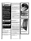
A. Install the Inner Flex Pipe -
1. Install the small gear clamp loosely around
the inner flexible vent pipe, push it back out
of the way.
2. Apply a bead of Mill-Pac Black (700° F) high
temperature sealant - Catalog No. 10K81
to the inner adaptor collar, approximately
1/2 inch from the end.
3. Pull and extend the inner flexible vent pipe.
4. Slide the inner flex pipe over the adaptor col-
lar. Ensure the flexible vent pipe completely
engages the adaptor collar to a distance of
1-3/4 inches from the end, and that it is free
from damage or tears.
5. Slide the gear clamp down and tighten it
fully to secure the flexible vent to the adaptor
inner collar approximately 3/4 inch from the
end of the flex.
6. Install three screws, 120 degrees apart,
through the flexible vent pipe and into the
adaptor collar just below the gear clamp to
provide additional security to the connec-
tion.
B. Install the Outer Flex Pipe -
1. Install the large gear clamp loosely around
the outer flexible vent pipe, push it back out
of the way.
2. Apply a bead of Mill-Pac Black (700° F) high
temperature sealant - Catalog No. 10K81
to the outer adaptor collar; to the grooves
of the collar which extend approximately 1
inch from the end and to the flat surface,
approximately 1-3/8 inches from the end.
3. Pull and extend outer flexible vent pipe.
4. Slide the outer flex pipe over the adaptor col-
lar. Ensure the flexible vent pipe completely
engages the adaptor collar to a distance of
1-3/4 inches from the end, and that it is free
from damage or tears.
5. Slide the gear clamp down and tighten it
fully to secure the flexible vent to the adaptor
outer collar approximately 3/4 inch from the
end of the flex.
6. Install three screws, 120 degrees apart,
through the flexible vent pipe and into the
adaptor collar just below the gear clamp to
provide additional security to the connec-
tion.
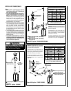
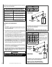
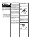
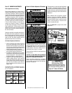
C. Route Flex Vent -
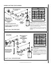
Ensure that the flex vent is properly routed to
provide the required clearance. Do not allow the
flexible vent to bend in a radius tighter than 5"
(127 mm). Refer to Figure 35. Space out the
internal flex vent spacers evenly - approximately
every 6 inches - and avoid kinking of inner pipe.
Support horizontal sections of flex with metal
straps at 2 foot (0.61 m) intervals.
E. Attach Flex Vent to Termination -
Secure Flex components can be purchased
separately and attached to bulk lengths of Se-
cure Flex flexible tubing cut to size at the job
site. Secure the flexible vent to the Secure Flex
terminations in the same manner (see Figure
34) as it was attached to the adaptor.
Note: Secure Flex vent must be attached to Secure
Flex terminations only. DO NOT substitute Secure
Vent terminations or the Secure Vent adaptor for
Secure Flex components. The collars of Secure
Flex terminations and adapters have a different
diameter than that used with the Secure Vent
pipe. Additionally, Secure Flex components
have an extended length center tube for use in
attaching the flexible vent.
Flexible Vent
Section
5” (127 mm)
Radius
Minimum
Figure 35