


Special offers from our partners!

Find Replacement BBQ Parts for 20,308 Models. Repair your BBQ today.

14
NOTE: DIAGRAMS & ILLUSTRATIONS ARE NOT TO SCALE.
TRAHCHTGNELNOITCESTNEV
noitceSlanimoN
)sehcni(htgneL
621426384
T
O
T
A
L
Q
T
Y
noitceSteN
)sehcni(htgneL
2/1-42/1-012/1-222/1-432/1-64
tneVfothgieHsnoitceStneVforebmuN
sehcnitf
44121100034
0515.21010034
5.451578.21110035
5.061573.31020035
5.271573.41000505
77157.41100506
38152.51010506
6815.51000044
5.091578.51100045
5.691573.61010045
5.502521.71011507
70252.71000606
5.112526.71100607
5.712521.81010607
5.922521.91001607
5.232573.91000055
73257.91100056
5.142521.02000707
6425.02100708
25212010708
46222001708
67232000808
97252.32000066
5.
082573.32100809
5.382526.32100067
5.982521.42010067
5.103521.52001067
5.013578.52000909
5135.621009001
5.523521.72000077
0335.72100078
63382010078
54357.8200001001
5.943521.9210001011
27313000088
5.673573.13100089
5.973526.1300011011
5.814578.43000099
32452.531000901
56457.8300000101
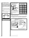
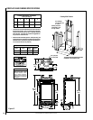
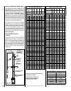
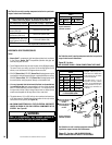
VENT SECTION LENGTH CHART
Nominal Section
Length (inches)
6 12 24 36 48
Net Section
Length (inches)
4 ½ 10 ½ 22 ½ 34 ½ 46 ½
Height of Vent Number of Vent Sections
*inches feet
T
O
T
A
L
Q
T
Y
TRAHCHTGNELNOITCESTNEV
lanimoN
htgneLnoitceS
)sehcni(
621426384
T
O
T
A
L
Q
T
Y
noitceSteN
)sehcni(htgneL
2/1-42/1-012/1-222/1-432/1-64
tneVfothgieHsnoitceStneVforebmuN
sehcnitf
5.4573.0100001
957.0200002
5.01578.0010001
5152.1110002
5.91526.12100
0
3
1257.1020002
5.22578.1001001
5.52521.2120003
5.13526.2030003
5.43578.2000101
5.73521.3111003
5.34526.3021003
5457.3002002
5.64578.3000011
5.94521.4102003
1552.4100012
5.55526.4012003
7557.4001102
6652.5022004
5.76526.5003003
9657.5000202
276103004
5.37521.6100203
5.97526.6010203
1857.6000112
095.7021014
5.
19526.7002013
3957.7000022
698101204
5.79521.8100023
2015.8200024
5.301526.8000303
8019100304
4115.9020024
71157.9105006
5.811578.9110305
6215.01001304
5.031578.01101305
53152.11006006
8315.11000404
5.931526.11000033
5.241578.11100405
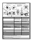
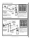
VENT SECTION LENGTH CHART
Nominal
Section Length
(inches)
6 12 24 36 48
Net Section
Length (inches)
4 ½ 10 ½ 22 ½ 34 ½ 46 ½
Height of Vent Number of Vent Sections
*inches feet
T
O
T
A
L
Q
T
Y
Note: Convert inches into metric equivalent
measurement, as follows:
Millimeters (mm) = Inches x 25.4
Centimeters (cm) = Inches x 2.54
Meters (M) = Inches x .0254
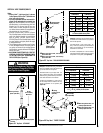
Effective Vent Length
Model Effective Length
SV4.5L6 4-1/2"
SV4.5L12 10-1/2"
SV4.5L24 22-1/2"
SV4.5L36 34-1/2"
SV4.5L48 46-1/2"
Table 7
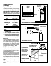
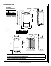
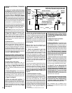
Figure 16
SV4.5CGV-1
Termination
SV4.5 F A OR
SV4.5FB Flashing
AND SV4.5SC
STORM COLLAR
SV4.5VF
Firestop/Spacer
SV4.5L6/12/24/36/48
V ent Sections
40' Max.
(12.2 M)
6' Min.
(1.8 M)
1" (25.4 mm)
Minimum
Clearance to
Combustibles
When using Secure Flex,
use Firestop/Spacer
SF4.5VF
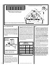
VERTICAL TERMINATION SYSTEMS (ROOF)
See Figures 16, and 24 through 26 on
Pages 14 and 17 and their associated Vertical
Vent Tables which illustrate the various vertical
venting configurations that are possible for use
with these appliances. Secure Vent™ pipe ap-
plications are shown in these figures; Secure
Flex™pipe may also be used. A Vertical Vent
Table summarizes each system’s minimum and
maximum vertical and horizontal length values
that can be used to design and install the vent
components in a variety of applications.
Both these vertical vent systems terminate
through the roof. The minimum vent height
above the roof and/or adjacent walls is speci-
fied in ANSI Z223.1-(latest edition) (In Canada,
the current CAN/CSA-B149 installation code)
by major building codes. Always consult your
local codes for specific requirements. A general
guide to follow is the Gas Vent Rule (refer to
Figure 5 on Page 6).
Vertical (Straight) Installation
(Figure 16)
Determine the number of straight vent sections
required. 4-1/2" (114 mm), 10-1/2" (267 mm),
22-1/2" (572 mm), 34-1/2" (876 mm) and
46-1/2" (1181 mm) net section lengths are
available (see Tables on this page and Page
32 - Vent Sections). Plan the vent lengths so
that a joint does not occur at the intersection of
ceiling or roof joists. Refer to the Vent Section
Length Chart.