


Special offers from our partners!

Find Replacement BBQ Parts for 20,308 Models. Repair your BBQ today.

9
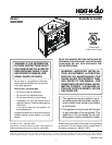
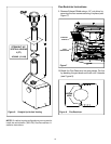
Installing the Fireplace
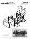
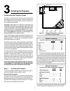
Step 1. Locating the Fireplace
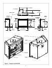
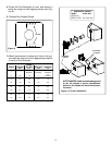
The following diagram shows space and clearance require-
ments for locating a fireplace within a room.
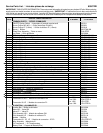
A B C D E
49” 22” 39 1/2” 56” 79”
Minimum Clearances
from the Fireplace to Combustible Materials
Inches mm
Glass Front ........................36 ..................... 914
Floor ....................................0........................ 0
Rear ................................... 1/2 ..................... 13
Sides ................................. 1/2 ..................... 13
Top ....................................3 1/2 .................... 89
Ceiling**..............................31 ..................... 787
Clearance Requirements
The top, back, and sides of the fireplace are defined by
stand-offs. The minimum clearance to a perpendicular wall
extending past the face of the fireplace is one inch (25 mm).
The back of the fireplace may be recessed 21 1/2 inches
(546 mm) into combustible construction.
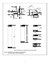
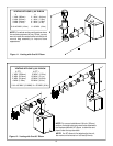
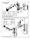
Minimum Clearances
from the Vent Pipe to Combustible Materials
Inches mm
Vertical Sections............... 1................. 25
Horizontal Sections
Top ...................................... 3................. 75
Bottom ................................ 1................. 25
Sides ..................................1................. 25
At Wall Firestops
Top ................................... 2 1/2.............63.7
Bottom .............................. 1/2 ............... 13
Sides ..................................1................. 25
* See Figure 3.
**The clearance to the ceiling is measured from the top
of the unit, excluding the standoffs (see Figure 40).
The distance from the unit to combustible construction
is to be measured from the unit outer wrap surface to
the combustible construction, NOT from the screw heads
that secure the unit together.
For minimum clearances, see the direct vent termination
clearance diagrams on pages 23 and 24 in this manual.
1/2” MIN. (13mm)
D
C
E
B
1” MIN. (25mm)
A
Figure 2. Fireplace Dimensions, Locations,
and Space Requirements
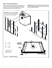
Constructing the Fireplace Chase
A chase is a vertical box-like structure built to enclose the
gas fireplace and/or its vent system. Vertical vents that run
on the outside of a building may be, but are not required to
be, installed inside a chase.
CAUTION: TREATMENT OF FIRESTOP SPACERS AND
CONSTRUCTION OF THE CHASE MAY VARY WITH THE
TYPE OF BUILDING. THESE INSTRUCTIONS ARE NOT
SUBSTITUTES FOR THE REQUIREMENTS OF LOCAL
BUILDING CODES. THEREFORE, YOUR LOCAL BUILD-
ING CODES MUST BE CHECKED TO DETERMINE THE
REQUIREMENTS FOR THESE STEPS.
Factory-built fireplace chases should be constructed in the
manner of all outside walls of the home to prevent cold air
drafting problems. The chase should not break the outside
building envelope in any manner.
This means that the walls, ceiling, base plate and cantilever
floor of the chase should be insulated. Vapor and air infiltra-
tion barriers should be installed in the chase as per regional
codes for the rest of the home. Additionally, Heat-N-Glo rec-
ommends that the inside surfaces be sheetrocked and taped
for maximum air tightness.
To further prevent drafts, the firestops should be caulked to
seal gaps. Gas line holes and other openings should be
caulked or stuffed with insulation. If the unit is being in-
stalled on a cement slab, we recommend that a layer of
plywood be placed underneath to prevent conducting cold
up into the room. Be sure to include spark arrestors for
woodburning units if they are required.
THE CHASE SHOULD BE CONSTRUCTED SO THAT ALL
CLEARANCES TO THE FIREPLACE ARE MAINTAINED
AS SPECIFIED WITHIN THIS INSTALLERS GUIDE.