


Special offers from our partners!

Find Replacement BBQ Parts for 20,308 Models. Repair your BBQ today.

20
!
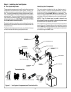
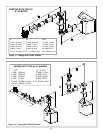
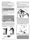
B. Installing Vent Components
After determining which set of starting collars will be used
(top or rear), follow venting instructions accordingly.
Venting Out the Rear Vent
Remove the installed rear seal cap from the rear starting
collars by cutting the strap at each end. (see Figure 18).
Follow the vent configuration tables accordingly.
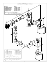
Remove the insulation from the REAR five inch flue, pull
the heat shield out from outside of the firebox.
WARNING: THE TOP HEAT SHIELD (INSIDE
THE FIREBOX) MUST REMAIN ATTACHED IF
THE VENT SYSTEM IS ATTACHED TO THE
REAR STARTING COLLARS. SEE FIGURE 18.
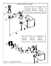
Venting Out the Top Vent
Remove the top vent collar seal cap and two pieces of
insulation inside the top two starting collars (See Fig-
ure 18).
Remove the heat shield from inside the TOP five inch flue
from outside of the firebox.
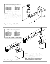
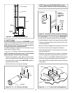
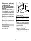
Figure 20.
Attaching First Vent Component to Starting Collars
STARTING
COLLAR
STOVE
SEALANT
BEAD
1 INCH
(25.4mm)
FIRST VENT
COMPONENT
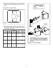
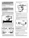
1. Attach the First Vent Component to Starting Collars
To attach the first vent component to the starting collars of
the fireplace:
• Apply a 3/8 inch (9.5mm) bead of stove cement around
the 5 inch (127mm) fireplace starting collar.
• Make sure that the fiberglass gasket supplied in the man-
ual bag seals between the first 8-5/8 inch (219mm) vent
component and the outer fireplace wrap. Using 2 self-
tapping screws from the manual bag, secure that gasket
to the outer wrap (see Figure 19).
WARNING: THE REAR VENT COLLAR SEAL
CAP MUST REMAIN ATTACHED TO THE REAR
VENT COLLARS IF THE VENT SYSTEM IS AT-
TACHED TO THE TOP STARTING COLLARS.
WARNING: FAILURE TO REMOVE INSULATION
IN THE SET OF COLLARS YOU ARE USING
COULD CAUSE A FIRE.
WARNING: YOU MUST LEAVE THE INSULATION
IN PLACE IN THE SET OF COLLARS YOU ARE
NOT USING.
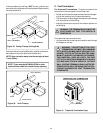
If your vertical vent component is over 10 feet, you may
want to install the vertical baffle (located in the bag containing
the install manual) to improve flame appearance. Center
the vertical baffle on the 5” flue being used, and with self
tapping screws secure the baffle to the inside of the firebox.
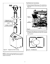
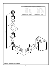
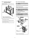
Figure 18
Venting Out Rear
Venting Out Top
!
!
!
HEAT
SHIELD
DISCARD
INSULATION
and
HEAT SHIELD
HEAT
SHIELD
INSULATION
DISCARD BOTH
PIECES and
HEAT SHIELD
SEAL
CAP
SEAL
CAP
Cut the seal cap
strap and remove white
gasket material.
CUT
HERE
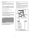
Figure 19. Fiberglass Gasket
FIRST VENT
COMPONENT
FIBERGLASS
GASKET
OUTER
WRAP
• Lock the vent components into place by sliding the con-
centric pipe sections with four (4) equally spaced interior
beads into the fireplace collar or previously installed com-
ponent end with four (4) equally spaced indented sections.
• When the internal beads of each 8-5/8 inch (219mm)
outer pipe line up, rotate the pipe section clockwise about
one-quarter (1/4) turn. The vent pipe is now locked together.
• The first 90° elbow installed in the vent system of a rear
venting fireplace MUST BE in a vertical position.
!
WARNING: A 3/8 INCH (9.5 MM) BEAD OF
STOVE CEMENT MUST BE PLACED AROUND
THE 5 INCH (127 MM) FIREPLACE STARTING COL-
LAR BEFORE ATTACHING THE FIRST VENT COM-
PONENT. FAILURE TO SEAL THIS JOINT MAY
CAUSE THE FIREPLACE TO OPERATE IMPROPERLY.