


Special offers from our partners!

Find Replacement BBQ Parts for 20,308 Models. Repair your BBQ today.
22
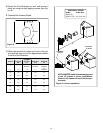
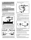
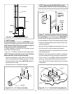
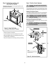
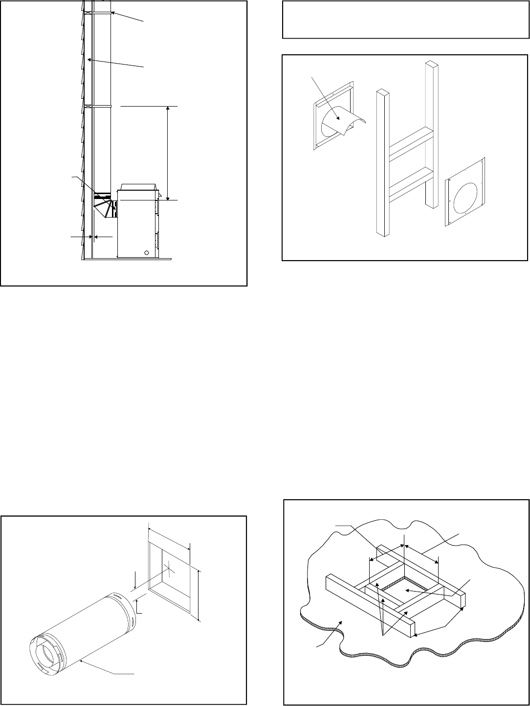
Figure 26. 12" x 12" Hole and Vent Pipe
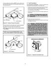
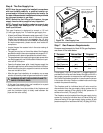
Figure 27. Heat Shield, Interior & Exterior Firestops
VENT PIPE
1" (25.4 mm)
12"
(305mm)
12"
(305mm)
TRIM HEAT
SHIELD IF TOO
LONG, ADD TO
SHIELD IF TOO
SHORT
EXTERIOR
FIRESTOP
INTERIOR
FIRESTOP
HEAT SHIELD
NOTE: There must be NO INSULATION or other
combustibles inside the framed firestop opening.
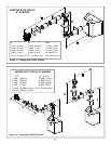
For Vertical Runs - One ceiling firestop is REQUIRED at
the hole in each ceiling through which the vent passes.
To install firestops for vertical runs that pass through ceilings:
• Position a plumb bob directly over the center of the verti-
cal vent component.
• Mark the ceiling to establish the centerpoint of the vent.
• Drill a hole or drive a nail through this centerpoint.
• Check the floor above for any obstructions, such as wir-
ing or plumbing runs.
• Reposition the fireplace and vent system, if necessary,
to accommodate the ceiling joists and/or obstructions.
• Cut an 11-inch X 11-inch (280mm X 280mm) hole through
the ceiling, using the centerpoint previously marked.
• Frame the hole with framing lumber the same size as the
ceiling joists.
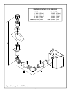
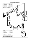
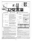
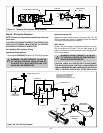
Figure 28. 11" x 11" Hole & New Framing Members
CEILING
NEW
FRAMING
MEMBERS
EXISTING CEILING
JOISTS
CHIMNEY
HOLE
11" (280 mm)
11" (280mm)
• Position the firestops on both sides of the hole previ-
ously cut and secure the firestops with nails or screws.
• The heat shields of the firestops MUST BE placed to-
wards the top of the hole.
• Continue the vent run through the firestops.
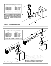
4. Install Firestops
For Horizontal Runs - Firestops are REQUIRED on both
sides of a combustible wall through which the vent passes.
NOTE: Model DVK-01TRD does not need an exterior
firestop on an exterior combustible wall.
To install firestops for horizontal runs that pass through
either interior or exterior walls:
• Cut a 12” x 12” (305mm x 305mm) hole through the wall.
NOTE: The center of the hole is one (1) inch (25.4mm)
above the center of the horizontal vent pipe.
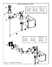
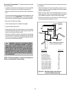
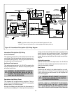
WALL BRACKET
WALL STUD
1 INCH MIN.
(25.4mm)
8 FT. (2.4m)
FLUE
OUTLET
Figure 25. Installing Support Brackets