


Special offers from our partners!

Find Replacement BBQ Parts for 20,308 Models. Repair your BBQ today.

21
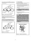
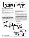
For Vertical Runs - The vent system must be supported
every eight (8) feet (2.4m) above the fireplace flue outlet by
wall brackets.
To install support brackets for vertical runs:
• Attach wall brackets to the vent pipe and secure the wall
bracket to the framing members with nails or screws.
3. Install Support Brackets
For Horizontal Runs - The vent system must be supported
every five (5) feet of horizontal run by a horizontal pipe support.
To install support brackets for horizontal runs:
• Place the pipe supports around the vent pipe.
• Nail the pipe supports to the framing members.
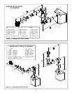
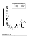
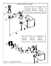
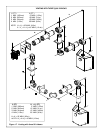
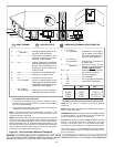
Figure 24. Adding Venting Components
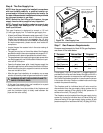
2. Continue Adding Vent Components
WARNING: INSTALLATION OF THIS FIRE-
PLACE REQUIRES THE USE OF HEAT
SHIELD 570-290 ABOVE THE FIRST 90
0
ELBOW IN
THE VENTING SYSTEM.
Figure 21
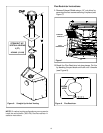
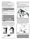
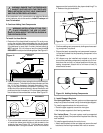
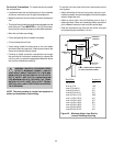
To Install the Heat Shield:
1. Determine if the heat shield is required. Do so by mea-
suring the vertical distance between the top horizontal
surface of the elbow to any combustible surface above.
If the distance is more than 4 inches, the heat shield is
NOT required. If it is 4 inches or less, the heat shield IS
REQUIRED. Install per the following steps. See Figure 21.
!
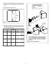
Figure 22
CORRECT INCORRECT
2. Fasten the shield in place using the four pilot holes pro-
vided in the part. The shield should be oriented such that
the 13 1/8 inch dimension (longest dimension) is run-
ning in the same direction the elbow is pointing. The
shield should be centered directly above the elbow, and
positioned so that it creates a 1/2 inch airspace between
the shield and the combustible surface. See Figure 22.
HEAT
SHIELD
3” MIN.
(76mm)
COMBUSTIBLE
SURFACE
COMBUSTIBLE SURFACE
DIRECTION
UP
HEAT SHIELD
90 ELBOW
0
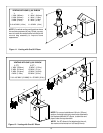
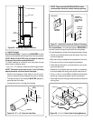
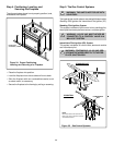
• If the combustible materials are not in place at the time
of install the elbow heat shield may be screwed to the
exhaust pipe (see Figure 23). Cut the tabs as shown
and bend down. Using the screws found in the manual
3”
(76mm)
SCREW
• Continue adding vent components, locking each succeed-
ing component into place.
• Ensure that each succeeding vent component is secure-
ly fitted and locked into the preceding component in the
vent system.
• 90° elbows may be installed and rotated to any point
around the preceding component’s vertical axis. If an el-
bow does not end up in a locked position with the pre-
ceding component, attach with a minimum of two (2)
sheet metal screws.
Figure 23
!
WARNING: ENSURE THAT THE FIBERGLASS
GASKET SUPPLIED WITH THE FIREPLACE
SEALS BETWEEN THE FIRST VENT COMPONENT
AND THE OUTER FIREPLACE WRAP.
If the installation is for a termination cap attached directly
to the fireplace, skip to the sections, Install Firestops and
Vent Termination.
bag secure the heat shield to the pipe maintaining 3” to
4” between the pipe and shield.