


Special offers from our partners!

Find Replacement BBQ Parts for 20,308 Models. Repair your BBQ today.

27
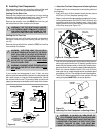
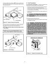
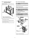
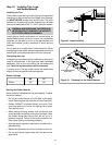
Figure 36. Gas Supply Line
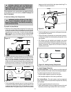
• At the gas line access hole, use insulation to re-pack
the space around the gas pipe.
• Insert insulation from the outside of the fireplace and
pack the insulation tightly to totally seal between the
pipe and the outer casing.
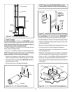
Step 6. The Gas Supply Line
NOTE: Have the gas supply line installed in accordance
with local building codes by a qualified installer ap-
proved and/or licensed as required by the locality. (In
the state of Massachusetts installation must be performed
by a licensed plumber or gas fitter).
NOTE: Before the first firing of the fireplace, the gas
supply line should be purged of any trapped air.
NOTE: Consult local building codes to properly size
the gas supply line leading to the 1/2 inch (13mm)
hook-up at the unit.
This gas fireplace is designed to accept a 1/2 inch
(13 mm) gas supply line. To install the gas supply line:
• A listed (and State of Massachusetts approved) 1/2 inch
(13mm) tee-handle manual shut-off valve and a listed
flexible gas connector are connected to the 1/2 inch
(13mm) inlet of the control valve. NOTE: If substituting
for these components, please consult local codes for
compliance.
• Locate the gas line access hole in the outer casing of
the fireplace.
• The gas line may be run from either side of the fireplace
provided the hole in the outer wrap does not exceed 2 1/2”
in diameter and it does not penetrate the actual firebox.
• The gap between the supply piping and gas access hole
can be plugged with non-combustible insulation to pre-
vent cold air infiltration.
• Open the fireplace lower grille, insert the gas supply line
through the gas line hole, and connect it to the shut-off valve.
• When attaching the pipe, support the control so that the
lines are not bent or torn.
• After the gas line installation is complete, use a soap
solution to carefully check all gas connections for leaks.
WARNING: DO NOT USE AN OPEN FLAME TO
CHECK FOR GAS LEAKS.
!
Step 7. Gas Pressure Requirements
Pressure requirements for Heat-N-Glo gas fireplaces
are shown in the table below.
Pressure Natural Gas Propane
Minimum 5.0 inches 11.0 inches
Inlet Pressure w.c. w.c.
Maximum Inlet 14.0 inches 14.0 inches
Gas Pressure w.c. w.c.
Manifold 3.5 inches 10.0 inches
Pressure w.c. w.c.
A one-eighth (1/8) inch (3 mm) N.P.T. plugged tapping is
provided on the inlet and outlet side of the gas control for a
test gauge connection to measure the manifold pressure.
Use a small flat blade screwdriver to crack open the screw
in the center of the tap. Position a rubber hose over the tap
to obtain the pressure reading.
The fireplace and its individual shut-off valve must be
disconnected from the gas supply piping system during
any pressure testing of the system at test pressures in
excess of one-half (1/2) psig (3.5 kPa).
The fireplace must be isolated from the gas supply piping
system by closing its individual shut-off valve during any
pressure testing of the gas supply piping system at test
pressures equal to or less than one-half (1/2) psig (3.5 kPa).
Use a wrench on
shut-off valve when
tightening gas line.
CONTROL
VALVE
GAS LINE
ACCESS HOLE
GAS
VALVE
MANUAL
SHUT-OFF
VALVE
FLEX
CONNECTOR