


Special offers from our partners!

Find Replacement BBQ Parts for 20,308 Models. Repair your BBQ today.

29
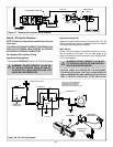
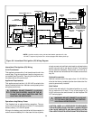
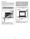
Intermittent Pilot Ignition (IPI) Wiring
3 Volt Transformer
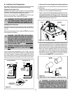
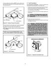
This appliance comes with a 3 volt transformer found in the
manual bag. Plug the transformer leads to the green con-
trol module (see Figure 39). Then plug the transformer into
the side outlet on the junction box.
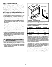
Appliance Requirements
This appliance requires that 110-120 VAC be wired to the
factory installed junction box. Maintain correct polarity when
wiring the junction box.
WARNING: DO NOT CONNECT 110-120 VAC
TO THE GAS CONTROL VALVE OR THE AP-
PLIANCE WILL MALFUNCTION AND THE
VALVE WILL BE DESTROYED.
Operation using Battery Power
This fireplace has an optional battery operation. The sys-
tem is fully functional with the use of two “D” size batteries
without ordinary 110-120 VAC power.
Wiring to the battery pack should be left disconnected in
order to conserve battery life. In the case of a loss of power,
!
!
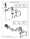
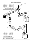
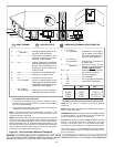
Figure 39. Intermittent Pilot Ignition (IPI) Wiring Diagram
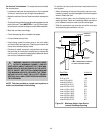
NOTE 1: Ignition module, valve, pilot and wall switch operate on 3 volts.
120 VAC is required at junction box unless equipped with battery back-up.
simply connect red and black wire leads to activate battery
power (connect red to red, black to black). The fireplace
can be used as necessary. Once power (110 VAC) is re-
stored, disconnect red and black wire leads to extend bat-
tery life.
Optional Accessories
Optional remote control kits require that 110-120 VAC be
wired to the factory installed junction box before the fire-
place is permanently installed.
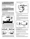
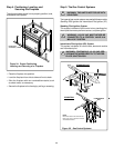
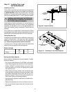
Wall Switch
Position the wall switch in the desired position on a wall.
Run a maximum of 25 feet (7.8 m) or less length of 18
A.W.G. minimum wire and connect it to the fireplace ON/
OFF switch pigtails.
WARNING: DO NOT CONNECT 110-120 VAC
TO THE WALL SWITCH OR THE CONTROL
VALVE WILL BE DESTROYED.
CAUTION: LABEL ALL WIRES PRIOR TO DISCONNEC-
TION WHEN SERVICING CONTROLS. WIRING ERRORS
CAN CAUSE IMPROPER AND DANGEROUS OPERA-
TION. VERIFY PROPER OPERATION AFTER SERVICING.
NEUTRAL
GROUND
REMOTE
CONTROL
HOT
LOW VOLTAGE
SEE NOTE 1
ON/OFF
WALL SWITCH
VALVE
BROWN
BROWN
RED
ORANGE
GREEN
BLACK
OPTIONAL
BATTERY
BACK-UP
BLACK (IGNITOR)
BLACK (SENSOR)
BLACK
GROUND TO
FIREPLACE
CHASSIS
PILOT ASSEMBLY
AND VALVE ASSEMBLY
MUST BE GROUNDED
(COMMON GROUND
WITH FIREPLACE
CHASSIS)
SPARK TO
PILOT IGNITOR
IGNITOR
MODULE
3V
120 VAC
JUNCTION BOX
T
R
A
N
S
F
O
R
M
E
R
3
V
FAN
TRANSFORMER OUTLET
PLUG-IN
3V TRANSFORMER
FLAME SPARKER /
SENSOR
LOW VOLTAGE
SEE NOTE 1
OPTIONAL
BATTERY
BACK-UP
IGNITION
MODULE
(3V)
ON/OFF
SWITCH
REM
TRANSFORMER
3V