


Special offers from our partners!

Find Replacement BBQ Parts for 20,308 Models. Repair your BBQ today.

Outdoor Lifestyles by Hearth & Home Technologies Inc. • Montana US-CAN • 4039-156 Rev K 7/11
16
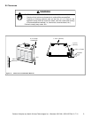
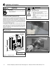
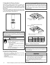
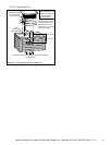
C. Assemble the Chimney Sections
Attach either a straight chimney section or an offset to the
top of the replace (depending on your installation require-
ment). Chimney sections are locked together by pushing
downward until the top section meets the stop bead on the
lower section.
The inner ue is placed to the inside of the ue section below
it. The outer casing is placed outside the outer casing of the
chimney section below it. See Figure 5.2.
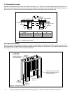
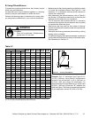
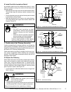
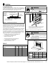
D. Install the Ceiling Firestops
• Mark and cut an opening in the ceiling for the ceiling
restop being used. See Figure 5.3.
• Frame the opening with the same size lumber used in the
ceiling joists.
• Install the ceiling restop.
Note: The ceiling restop MUST be nailed to the bottom
of the ceiling joists EXCEPT when the space above is
uninsulated and the attic insulation shield is not being used
(see Figure 5.5). When the attic insulation shield is used
the ceiling restop may be above or below the joist of an
insulated ceiling.
Note: You must provide support for the pipe during
construction and check to be sure inadvertent loading has
not dislodged the chimney section from the replace or at
any chimney joint.
Note: Inner flue and outer liner sections cannot be
disassembled once locked together. Plan ahead to ensure
the proper installation height is achieved with the selected
chimney components.
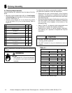
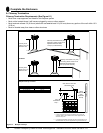
• Ceiling restops must be used at ceiling/oor.
• Chase construction requires ceiling restops at each
oor or every 10 ft ( 3.05 m) of clear space.
• Use same dimensional lumber as joists.
Ceiling restop slows spread of re and reduces cold air
inltration.
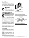
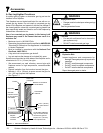
CAUTION
Figure 5.2 Assembling Chimney Sections
Fire Risk
Do NOT install substitute or damaged
chimney components.
• MUST use chimney system described in
this manual.
• NO OTHER chimney components may
be used.
Substitute or damaged chimney components
may impair safe operation.
WARNING
ROOM ABOVE (non-insulated ceiling)
ATTIC ABOVE (insulated ceiling)
B
A
Ceilng firestop from
bottom
Ceiling firestop from
top
Note: Use same dimensional lumber for framing
ceiling firestop and joists.
Figure 5.3 Installing the Ceiling Firestop
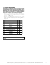
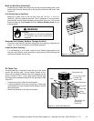
Catalog #
A B
in. mm in. mm
FS538 17 432 17 432
FS540 17 432 26 660