


Special offers from our partners!

Find Replacement BBQ Parts for 20,308 Models. Repair your BBQ today.
Outdoor Lifestyles by Hearth & Home Technologies Inc. • Montana US-CAN • 4039-156 Rev K • 7/11
15
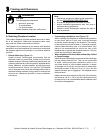
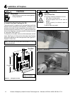
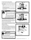
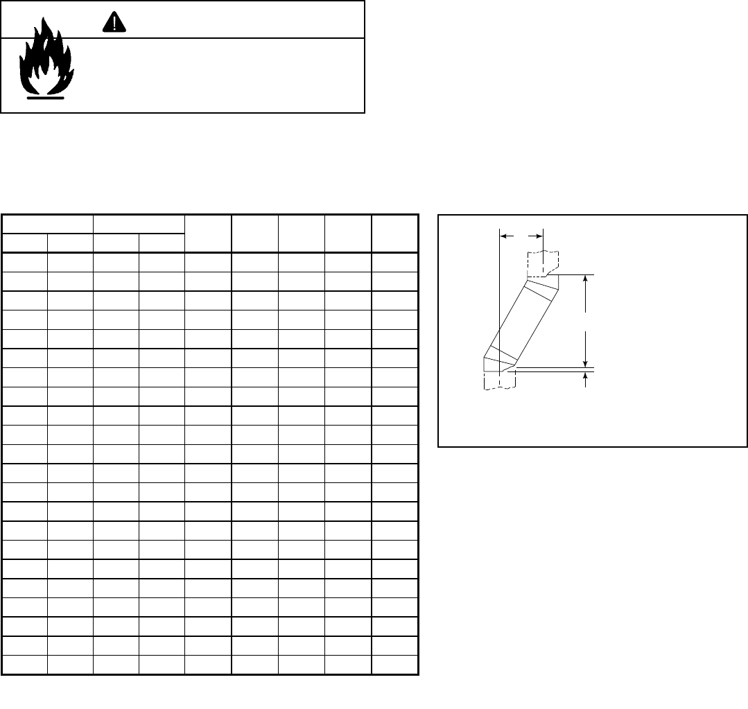
B. Using Offsets/Returns
To bypass any overhead obstructions, the chimney may be
offset using an offset/return.
An offset and return may be attached together or a chimney
section(s) may be used between an offset and return.
Perform the following steps to determine the correct chim-
ney component combination for your particular installation:
• Measure how far the chimney needs to be shifted to enable
it to avoid the overhead obstacle. See Figure 5.1. Use
dimension “A” to determine chimney section required to
achieve the needed shift.
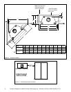
• After determining the offset dimension, refer to Table 5.2
and nd the “A” dimension closest to but not less than the
distance of shift needed for your installation.
• The “B” dimension that coincides with the “A” dimension
represents the required vertical clearance that is needed
to complete the offset and return.
• Read across the chart and nd the number of chimney
sections required and the model number of those particular
chimney parts.
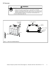
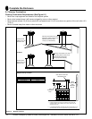
• Whenever the chimney penetrates a oor/ceiling, a ceiling
restop must be installed.
• The effective height of the replace assembly is measured
from the base of the replace to the top of the starter collar.
See Dimensions in Section 12.
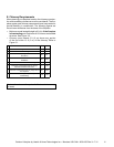
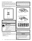
Table 5.2
A
B
1-1/4 in. (32 mm)
OVERLAP
Figure 5.1 Chimney Offset/Return
Example: Your “A” dimension from Figure 5.3 is
14 1/2 in. (368 mm). Using Table 5.2 the dimension
closest to, but not less than 14 1/2 in. (368 mm) is
15 3/4 in. (400 mm) using a 30° offset/return. It is
then determined from the table that you would need
36 5/8 in. (930 mm) (Dimension “B”) between the
offset and return. The chimney components that best
t your application are two SL1112s or SL412s.
Fire Risk
• Draft will be restricted if offsets/returns
greater than 30° are used.
WARNING
A B
SL1106
SL406
SL1112
SL412
SL1118
SL418
SL1136
SL436
SL1148
SL448in. mm in. mm
4 7/8 124 17 7/8 454 - - - - -
7 1/4 184 2 2 559 1 - - - -
9 3/4 248 26 1/8 664 2 - - - -
10 1/4 260 27 1/4 692 - 1 - - -
12 3/4 324 31 3/8 797 1 1 - - -
13 1/4 337 32 3/8 822 - - 1 - -
15 3/4 400 36 5/8 930 - 2 - - -
18 1/8 460 40 3/4 1035 1 2 - - -
18 3/4 476 41 3/4 1060 - 1 1 - -
21 3/4 552 47 1194 - - 2 - -
22 1/4 565 48 1219 - - - 1 -
24 3/4 629 52 1/8 1324 1 - - 1 -
27 3/4 705 57 3/8 1457 - 1 - 1 -
28 1/4 718 58 3/8 1483 - - - - 1
30 3/4 781 62 1/2 1588 1 - - - 1
33 3/4 857 67 3/4 1721 - 1 - - 1
36 3/4 933 73 1854 - - 1 - 1
39 3/4 1010 78 1/8 1984 - - - 2 -
41 1/8 1045 82 3/8 2092 1 - - 2 -
45 3/4 1162 88 1/2 2248 - - - 1 1
48 1/8 1222 92 3/4 2356 1 - - 1 1
51 3/4 1314 98 7/8 2511 - - - - 2
Proper assembly of air cooled chimney parts results in an overlap of chimney joints
of 1-1/4 in. (32 mm). Effective length is built into this table.