


Special offers from our partners!

Find Replacement BBQ Parts for 20,308 Models. Repair your BBQ today.

Heat & Glo Lifestyle Collection • Dakota 42-CE • 4036-915 Rev I • 11/07 9
6
6
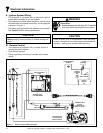
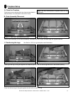
Gas Information
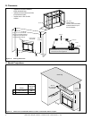
Note: Gas line MUST be run from right side of fi replace.
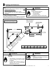
WARNING
CHECK FOR GAS LEAKS
Fire Risk
Explosion Risk
Asphyxiation Risk
• Check all fi ttings and connections.
• Do not use open fl ame.
• After the gas line installation is complete,
all connections must be tightened and
checked for leaks with a commercially
available, non-corrosive leak check
solution. Be sure to rinse off all leak check
solution following testing.
Fittings and connections may have loosened
during shipping and handling.
WARNING
Fire Risk
Explosion Risk
High pressure will damage valve.
• Disconnect gas supply piping BEFORE
pressure testing gas line at test pressures
above 60 mbar.
• Close the manual shutoff valve BEFORE
pressure testing gas line at test pressures
equal to or less than 60 mbar.
A. Gas Pressure Requirements
Pressure requirements for Heat & Glo gas fi replaces are
shown in Table 1 below.
Two taps are provided on the outlet side of the gas control
for a test gauge connection to measure the inlet and outlet
pressures. These inlet and outlet pressure taps can be ac-
cessed through the internal valve access panels as shown
in Section 11: Maintaining and Servicing the Fireplace.
The fi replace and its individual shut-off valve must be dis-
connected from the gas supply piping system during any
pressure testing of the system at test pressures in excess
of 60 mbar.
If the fi replace must be isolated from the gas supply piping
system by closing an individual shut-off valve, it must be of
the handle-less type.
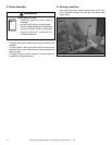
B. Gas Connection
Note: Have the gas supply line installed in accordance
with local building codes by a qualified installer
approved and/or licensed as required by the locality.
Table 1
Natural Gas
(G20)
Propane
(G31)
Butane
(G30)
Natural Gas
(G25)
Inlet Pressure 20mbar 37 or 50mbar 30 or 50mbar 25mbar
Manifold Pressure 4-8.7 mbar 24mbar 24mbar
8.7mbar
Gas Rate
1.68
m3
/
h
.62
m3
/
h
.42
m3
/
h
1.68
m3
/
h
Max.Input (NETCV) 16.5 kW 15.0 kW 13.7kW 14.0 kW
Burner Injector DMS 25 DMS 44 DMS 46 DMS 25
Pilot Injector 51 30 30 51
Incoming gas line should be piped into the valve compart-
ment and connected to the ISO 7-Rp 1/2 (BSP Rp 1/2)
threaded gas inlet connection on the manual shutoff valve.
Note: Before the fi rst fi ring of the fi replace, the gas
supply line should be purged of any trapped air.
Note: Consult local building regulations to properly
size the gas supply line leading to the (Rp 1/2 in.)
hook-up at the unit.