


Special offers from our partners!

Find Replacement BBQ Parts for 20,308 Models. Repair your BBQ today.

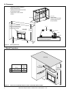
10 Heat & Glo Lifestyle Collection • Dakota 42-CE • 4036-915 Rev I • 1/07
Battery polarity must be correct or module damage will
occur.
CAUTION
7
7
Electrical Information
Label all wires prior to disconnection when servicing
controls. Wiring errors can cause improper and dangerous
operation. Verify proper operation after servicing.
CAUTION
Shock Risk
• Replace damaged wire with type 105° C rated wire.
• Wire must have high temperature insulation.
WARNING
BATTERY PORT
(4 AA BATTERIES)
VALVE
PILOT
IGNITION MODULE
6VDC
ON/OFF
SWITCH
THERMOCOUPLE
BLOCK
(CONNECTED TO
BACK OF VALVE)
PILOT GAS LINE
CONNECTED TO
BACK OF VALVE
IGNITION
MODULE
(6V)
ON/OFF
WALL SWITCH
VALVE
FLAME SPARKER/
SENSOR
ANT.
REMOTE
CONTROL
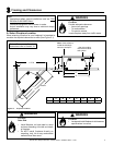
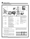
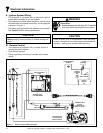
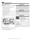
A. Ignition System Wiring
• This fi replace is equipped with an electronic ignition
system which operates on a 6 volt system.
• The batteries are located within the ignition module which
is located within the external control box. A wiring diagram
is shown in Figure 7.1.
• The battery pack requires four AA batteries (not included).
See Section 11.B for battery replacement.
Figure 7.1 Electronic Ignition Wiring Diagram
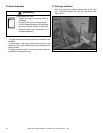
B. Remote Control
• This fi replace is equipped with a remote control to
operate the ignition system.
• 9 volt battery required.
• Follow operating instructions included with remote
control.