


Special offers from our partners!

Find Replacement BBQ Parts for 20,308 Models. Repair your BBQ today.

8 U32-2 FPI Direct Vent Gas Insert
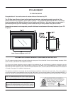
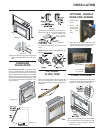
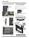
OPTIONAL
BRICK PANEL
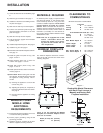
1) Unwrap the brick pattern panels from the
protective wrapping.
2) Remove the glass front if it is already
installed, see page 11.
3) Put the rear brick panel flat against the back
of the unit.
Diagram 1
Diagram 2
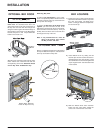
GAS PIPE
PRESSURE TESTING
The appliance must be isolated from the gas
supply piping system by closing its individual
manual shut-off valve during any pressure
testing of the gas supply piping system at test
pressures equal to or less than 1/2 psig. (3.45
kPa). Disconnect piping from valve at pres-
sures over 1/2 psig.
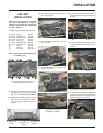
The manifold pressure is controlled by a regu-
lator built into the gas control, and should be
checked at the pressure test point.
Note: To properly check gas pressure,
both inlet and manifold pressures
should be checked using the valve
pressure ports on the valve.
1) Make sure the valve is in the "OFF" position.
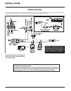
INSTALLATION
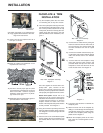
9) Connect the 2nd liner to the exhaust collar
marked with an "E", seal connection with
high temperature silicone. Secure with gear
clamp.
NOTE: 1) Final gas connection should be made
after unit is in place to avoid damage to
line when pushing the unit into position.
2)Mill-pac may be used instead of high
temperature silicone and screws may
be used instead of gear clamps at
connections of liner to inlet and vent
collars.
4) Before installing the side brick panels,
loosen the screws for the brick tabs enough
so that you can slide the brick tabs on to the
screws easily but that the tabs are secure.
For the location of the side brick tab screws
see diagram 1.
5) Remove the brick tabs and slide the side
brick panels into position. See diagram 1.
Install the brick tabs. See diagram 2.
2) Loosen the "IN" and/or "OUT" pressure
tap(s), turning counterclockwise with a 1/
8" wide flat screwdriver.
3) Attach manometer to "IN" and/or "OUT"
pressure tap(s) using a 5/16" ID hose.
4) Light the pilot and turn the valve to "ON"
position.
5) The pressure check should be carried out
with the unit burning and the setting should
be within the limits specified on the safety
label.
6) When finished reading manometer, turn off
the gas valve, disconnect the hose and
tighten the screw (clockwise) with a 1/8"
flat screwdriver.
Note: Screw should be
snug, but do not over tighten.
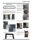
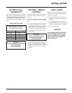
GAS INSERT
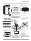
AERATION SYSTEM
The air shutter can be adjusted by moving the
adjusting wire up or down. The wire is ac-
cessed through the bottom louver opening.
Open the air shutter for a blue flame or close
for a yellower flame. The burner aeration is
factory set but may need adjusting due to either
the local gas supply or altitude.
Minimum Air Shutter Opening:
3/16" Natural Gas
1/4" Propane
CAUTION: Carbon will be produced if air
shutter is closed too much.
Note: any damage due to carboning re-
sulting from improperly setting the aer-
ation controls is NOT covered under
warranty.
Note: Aeration Adjustment should only
be performed by an authorized FPI
Installer at the time of installation
or service.
Aeration Adjustment Wire
PULL= Open
PUSH = Close