


Special offers from our partners!

Find Replacement BBQ Parts for 20,308 Models. Repair your BBQ today.

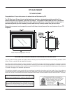
10 U32-2 FPI Direct Vent Gas Insert
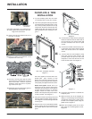
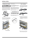
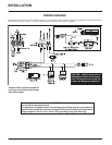
Diagram 3
Rear View: Trim Assembly
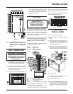
Diagram 2
Rear View: Faceplate Assembly
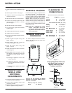
Diagram 1
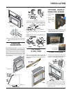
FACEPLATE & TRIM
INSTALLATION
1) Lay the faceplate panels flat, face down
on something soft so they don't scratch.
2) Take the top faceplate and align the holes
in it with the holes in the side panels. Using
the screws provided, attach from the top
of the panel (the holes in the top panel are
slightly larger than the holes in the side
panel to facilitate easier installation). Dia-
gram 1.
Hint: Don't tighten the screws down com-
pletely at this point, continue on with
steps 3 and 4 and do a trial fit to the unit.
Make any necessary adjustments and when
it fits properly then tighten down the screws.
Hearth Trim Option: Hearth Trim is an
option that can be used to finish off the
installation when the bottom of the fireplace
is higher than the hearth or to raise the
fireplace. Attach the Hearth Trim to the
bottom of the faceplate side panels with the
screws provided. See Diagram 1.
3) Using the connectors provided, join the left
side trim (with the ON/OFF switch) to the top
trim. Diagram 2. Connect the right side trim
to the top trim.
4) Place the trim on the assembled faceplate
panels, aligning the wire connections from
the switches with the notch on the left side
panel.
5) Connect the fan switch wires by taking the
black and red wires with the male ends (in
the grey harness) and connect them with
the wire connectors from the fan speed
control.
6) Connect the ON/OFF switch wires by tak-
ing the black and red wires with the female
ends and connect them to the ON/OFF
switch.
7) Tuck the wires into the faceplate to keep
them away from the insert using the clip
provided. Attach the clip to the rear of the
faceplate to ensure that the wires do not
touch the side of the unit. Diagram 3.
8) The power cord should be run behind the
faceplate panel.
9) Attach the brass trim to the faceplate by
drilling a 1/8" hole through into the faceplate
using the hole in the trim as a guide. Fasten
the trim to the faceplate panels using the
plated screws. Diagram 4.
10)Attach the faceplate panels to the insert
body using the 4 remaining black screws.
Diagram 5.
INSTALLATION
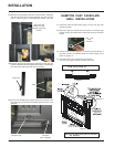
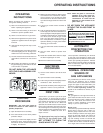
10)Place the embers and Rockwool on the
exposed front burner tray.
11)Test fire to ensure proper light off (make
sure flame flows smoothly from one end of
burner to the other. If there is any flame
hesitation, check that area for any block-
age of the burner port.
12)Install flush glass and optional bay glass as
per instructions in this manual.
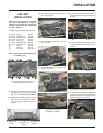
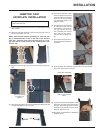
9) Place Front Left Log G)02-44 onto the 2
front pins as shown.
G)02-44
F)02-48
B)02-45
Bracket
A)02-43
Front edge of
rear burner
The bottom right edge of Log F)02-48 must
sit snugly against the bracket and the front
edge of the rear burner.
Side View
C)02-56
A)02-43
B)02-45
F)02-48
D)02-46
G)02-44
E)02-47