


Special offers from our partners!

Find Replacement BBQ Parts for 20,308 Models. Repair your BBQ today.

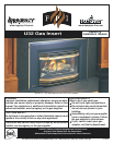
6 U32-2 FPI Direct Vent Gas Insert
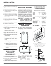
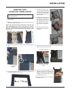
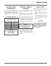
MATERIALS REQUIRED
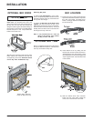
No electrical power supply is required for the
gas control to operate. A 120 Volt AC power
cord is hooked up to the fan. Plug the 3 wire
cord into a suitable receptacle. Do not cut the
ground terminal off under any circum-
stances. When connected with 120 volts, the
appliance must be electrically grounded in ac-
cordance with local codes, current version of
CSA C22.1 (in Canada) or in the absence of
local codes, with the National Electrical Code
ANSI/NFPA 70-1987.
NOTE: This unit is equipped with a heat
sensor thermodisc which will
prevent the blower from operat-
ing until the unit reaches the cor-
rect temperature.
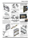
INSTALLATION
1) Check all clearances to combustibles, page
6.
2) Make the gas connection. See page 7.
3) Install the 3" flue liner to the sliding connec-
tor plate. See page 7.
4) Slide the unit half way into the fireplace.
5) Pull the vent connector plate through the
tapered brackets and fasten to the front
plate. See page 7.
6) Slide the unit fully into the fireplace.
7) Test gas pressure, page 8. Check aeration
system, page 8.
8) Install the optional brick panels. See page 8.
9) Install the log set. See page 9.
10)Assemble and install the faceplate and trim.
See page 10.
11)Install the glass front (flush or bay). See
pages 10 and 11.
12)Install optional glass trim, or door fire
screens. See pages 11 and 12.
13)Install both louvers (flush or bay). See
pages 11 and 12.
14)Install optional remote control or wall ther-
mostat, pages 15.
15) Final check: Before leaving this unit with
the customer, the installer must ensure that
the appliance is firing correctly. This in-
cludes:
a) Clocking the appliance to ensure the
correct firing rate.
b) Adjusting the primary air, if required, to
ensure that the flame does not carbon.
See page 8.
c) Ensuring that the appliance is venting
correctly.
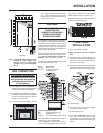
MANUFACTURED
MOBILE HOME
ADDITIONAL
REQUIREMENTS
1) Ensure that structural members are not cut
or weakened during installation.
2) Ensure proper grounding using the #8
ground lug provided.
3) Appliance must be anchored to the floor
with the supplied anchoring methods.
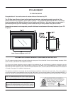
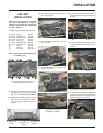
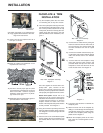
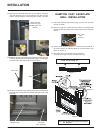
MINIMUM FIREPLACE
DIMENSIONS
The minimum fireplace clearances & dimen-
sions for the FPI gas insert are shown in the
following diagrams:
Diagram 1
Combustible Mantel Clearances
with Bay & Flush Louvers in
Masonry and Factory Built
Fireplace Installation
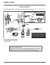
Diagram 2
CLEARANCES TO
COMBUSTIBLES
Minimum Clearances to Combustibles
From Unit
Sides A 10" / 255 mm
Ceiling B 47.5" / 1205 mm
Mantel C see Dia. 2 & 3
From Standard Surround (26" x 40")
Sides D 4" / 100 mm
Ceiling E 41.5" / 1055 mm
Mantel see Dia. 2 & 3
Max. Mantle Depth G 12" / 305 mm
(see Dia. 2)
Hearth Height H 0" / 0 mm
Hearth Depth I 16" / 405 mm
Hearth Width J 40" / 1015 mm
Min. Alcove Width K 48" / 1220 mm
Max. Alcove Depth L 36" / 915 mm
*Note: If you are installing the Molded
Faceplate, the minimum fireplace dimen-
sions are as follows:
Width (at front):29" (737mm)
Depth: 15" (381mm)