


Special offers from our partners!

Find Replacement BBQ Parts for 20,308 Models. Repair your BBQ today.

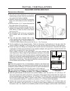
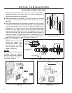
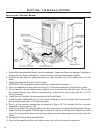
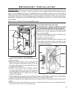
Figure 36: Optional Blower (Fan) Installation.
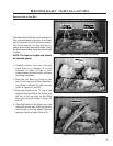
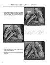
1. Remove the pre-assembled blower from the packaging. Inspect the blower for damage. If damage is
noticed call your dealer, distributor or courier company and have components replaced.
2. Remove the side panel by pulling the panel up, slide the panel out of the bottom slots, and set
aside.
3. Install the temperature sensor into the holder.
IMPORTANT: The temperature sensor must be in contact with the rebox.
4. Open the pedestal door and remove the four (4) T-20 screws holding the Control Panel in place.
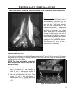
5. Fit the Fan Unit into the cabinet being careful to work around the gas and pilot lines. The fan will
t up behind the gas valve. With an extension driver, fasten the Fan Unit in place with four (4) T-20
screws provided.
6. Install the Fan Controller into the provision in the Control Panel.
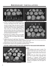
7. Install the Strain Relief plate into the stove back by tting the tab on the plate into the stove back
and secure the plate with a T-20 screw provided.
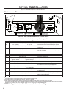
8. Plug in all the electrical connections as indicated in Figure 35. This includes the Fan Controller,
Temperature sensor and Fan Unit.
9. Using the provided T-20 screw, located on the right mount below and behind the Temperature Sensor,
fasten the wire tie supplied. With the wire tie capture the fan wires including the temperature switch
wires, this will secure the wires and route them away from hot surfaces and out of the way of the fan
blades
10. Re-install the Control Panel and Side Panel.
11. Plug the fan assembly into the wall outlet and turn the unit on to ensure fan operation.
Initial Installation
INSTALLATION OF OPTIONAL BLOWER:
22