


Special offers from our partners!

Find Replacement BBQ Parts for 20,308 Models. Repair your BBQ today.

12
Maintenance And Service
FUEL CONVERSION:
TO BE INSTALLED BY A QUALIFIED SERVICE AGENCY ONLY
Please read and understand these instructions before installing.
Warning: This conversion kit shall be installed by a qualied service agency in accordance
with the manufacturer’s instructions and all applicable codes and requirements of the
authority having jurisdiction. If the information in these instructions is not followed
exactly, a re, explosion or production of carbon monoxide may result causing property
damage, personal injury or loss of life. The qualied service agency is responsible for
the proper installation of this kit. The installation is not proper or complete until the
operation of the converted appliance is checked as specied in the manufacturer’s
instructions supplied with the kit.
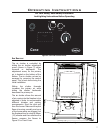
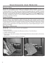
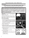
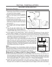
Figure 14: Removing the orice.
Kit Parts List:
Orice (NG - PO512-42 DMS or LP - PO512-54 DMS)
Installation instruction sheet
Carefully inspect all parts supplied with this conversion kit. If
any parts have been damaged or are missing, contact your
dealer, distributor or courier company to have them replaced
before starting this installation.
Conversion Kit Installation:
1. Turn control knob on the gas valve to the “OFF” position
and shut the gas supply off at the shut-off valve upstream
of the unit. CAUTION: The gas supply must be shut off
prior to disconnecting the electrical power and before
proceeding with the conversion. Allow the valve and unit
to cool down to room temperature.
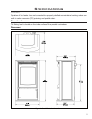
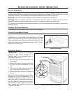
2. Remove the glass door as shown in the MAINTENANCE AND
SERVICE - GLASS DOOR REMOVAL.
3. Carefully remove the log set.
4. Slide the burner back just far enough so the front edge of
the burner does not catch on the front lip of the rebox.
Lift the front of the burner up and out of the rebox. See
MAINTENANCE AND SERVICE - BURNER REMOVAL & INSTALLATION.
5. Convert the burner orice:
a) Remove the main burner orice with a ” socket
(refer to Figure 14).
b) Install the alternate orice from the kit.
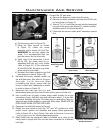
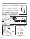
6. Convert the pilot injector:
a) Loosen the pilot stem a half turn using a
7
/16” wrench
(refer to Figure 15).
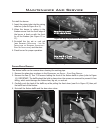
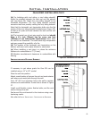
b) Slide the tab to the other side of the pilot stem (refer
to Figures 16 & 17).
c) Tighten the pilot stem.
Figure 15: Turning Pilot Stem.
Natural Gas Position:
NA Stamp Visible
.020” (0.51mm) Hole Size
L.P. Gas Position:
LP Stamp, Hole, & Red
Colour Code Visible
.014” (0.36mm) Hole Size
Figure 16: NG & LP Gas Positions on Pilot.