


Special offers from our partners!

Find Replacement BBQ Parts for 20,308 Models. Repair your BBQ today.
www.desatech.com
113134-01B 17
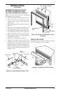
8. Place cardboard or other protective material
on top of hearth base. Carefully set fireplace
on protective material, with back of fireplace
inside mantel opening.
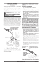
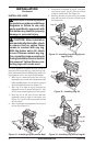
9. Attach flexible gas line to fireplace gas regula
-
tor. See Connecting Fireplace to Gas Supply,
page 14.
10. Route electrical cord(s) through access holes
in either side of fireplace with bushing. Plug
electrical cord(s) into electrical outlet.
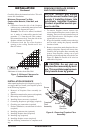
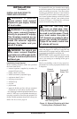
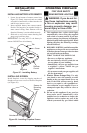
11. Carefully insert fireplace into cabinet mantel (see
Figure 23). Be careful not to scratch or damage
hearth base, cabinet mantel, or any laminate trim
on hearth base. Remove protective material from
top of hearth base and from front of fireplace (if
any).
Note: You can secure fireplace to hearth
or floor. Open lower louver. Locate screw
holes in bottom of base. Tighten wood screws
through these holes and into hearth or floor.
12. Check all gas connections for leaks. See
Checking Gas Connections, page 15.
INSTALLATION
Continued
Figure 23 - Inserting Fireplace Into
Cabinet Mantel
BUILT-IN FIREPLACE
INSTALLATION
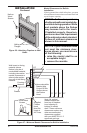
Built-in installation of this fireplace involves install-
ing fireplace into a framed-in enclosure. This makes
the front of fireplace flush with wall. If installing
a mantel above the fireplace, you must follow the
clearances shown in Figure 27, page 18. Follow
the instructions below to install the fireplace in
this manner.
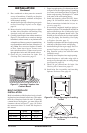
Actual Framing
Height 32
3
/8" 33"
Front Width 34
5
/16" 35
1
/2"
Depth 16
11
/16" 17
3
/4"
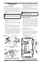
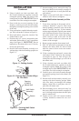
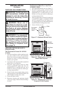
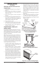
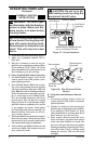
1. Frame in rough opening. Use dimensions shown
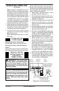
in Figure 24 for the rough opening. If installing
in a corner, use dimensions shown in Figure 25
for the rough opening. The height is 33" which
is the same as the wall opening above.
2. Install and properly ground GA3555, three-
prong 120 volt electrical outlet, in fireplace.
Follow instructions included in kit (see
Ac-
cessories, page 36).
3. If not already completed, install gas piping to
fireplace location. This installation includes an
approved flexible gas line (if allowed by local
codes) after the equipment shutoff valve. The
flexible gas line must be the last item installed
on the gas piping. See Installing Gas Piping
to Fireplace Location,
page 13.
4. Carefully set fireplace in front of rough opening
with back of fireplace inside wall opening.
5. Attach flexible gas line to gas supply. See Con
-
necting Fireplace to Gas Supply, page 14.
6. Plug electrical cord(s) into electrical outlet
installed in step 2.
7. Carefully insert fireplace into rough opening.
8. Attach fireplace to wall studs using nails or
wood screws through holes in nailing flange
(see Figure 26, page 18).
9. Check all gas connections for leaks. See
Checking Gas Connections, pages 15.
10. Install trim. See Assembling and Attaching
Optional Perimeter Trim,
page 19.
35
1
/2"
17
3
/4"
33"
39
3
/8"
27
7
/
8
"
55
5
/8"
35
1
/2"
Figure 24 - Rough Opening for Installing
in Wall
Figure 25 - Rough Opening for Installing
in Corner