


Special offers from our partners!

Find Replacement BBQ Parts for 20,308 Models. Repair your BBQ today.
www.desatech.com
113134-01B
12
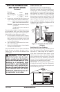
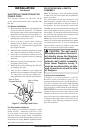
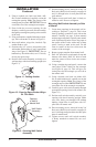
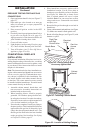
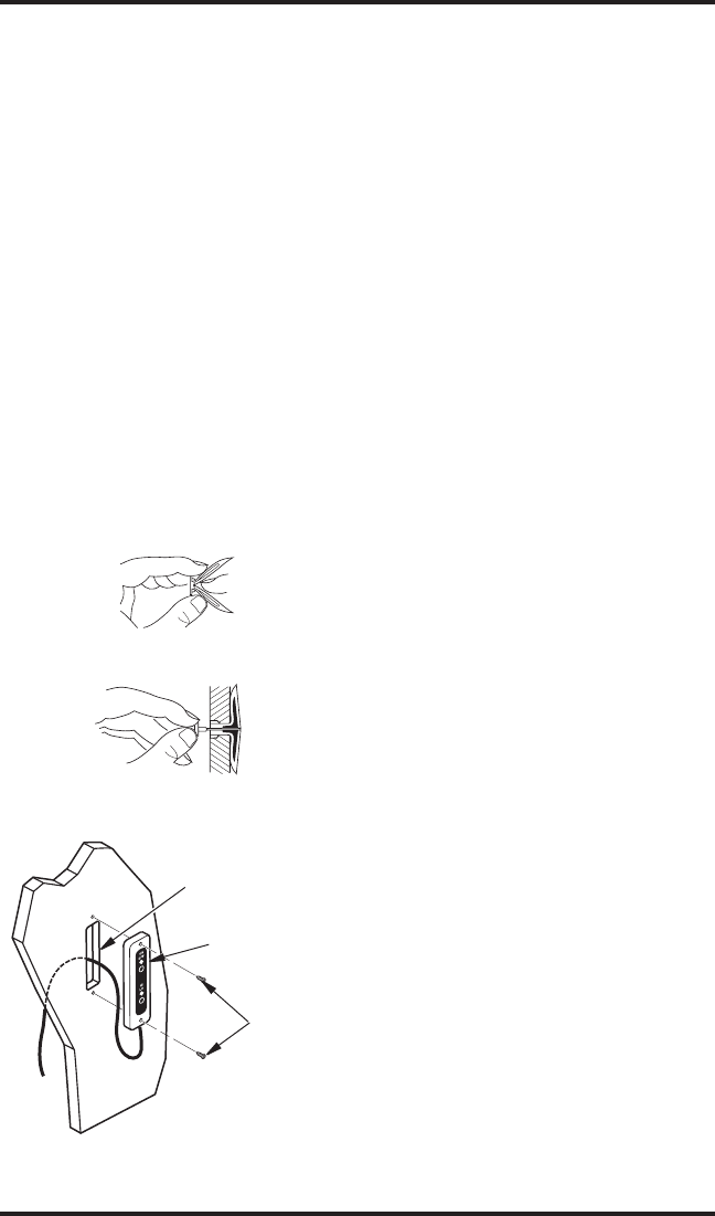
Figure 11 - Folding Anchor
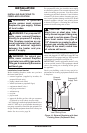
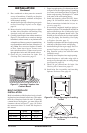
Figure 12 - Popping Open Anchor Wings
for Thin Walls
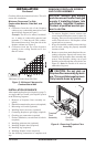
11. Using a keyhole saw, hack saw blade, drill,
file, or other suitable tool, carefully cut out the
rectangular opening. Note: The corners of the
rectangle may be round. IMPORTANT: Do not
exceed the size of the rectangle on template.
12. From inside the recessed opening for the
fireplace, carefully pass wall switch assembly
through the rectangular opening to the outside
of the wall.
13. Using wall anchors supplied in hardware pack
-
age, fold wall anchor as shown in Figure 11.
14. Insert wall anchor, wings first, into hole. Tap
anchor flush to wall.
15. For thin walls (1/2" or less), insert red key into
wall anchor. Push red key to “pop” open anchor
wings. See Figure 12. IMPORTANT: Do not
hammer key! For thick walls (over 1/2" thick),
do not pop open wings.
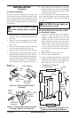
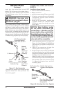
16. Position wall switch assembly vertically over
wall openings with decal lettering upright (see
Figure 13).
INSTALLATION
Continued
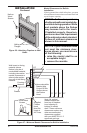
Figure 13 - Securing Wall Switch
Assembly
Screws
Wall Switch
Assembly
Opening
in Wall or
Mantel Wall
17. Insert mounting screws, removed in step 2 of
Relocating Wall Switch Assembly on pages 10
and 11, through holes in wall plate and into
wall anchors.
18. Tighten screws until wall plate is firmly at
-
tached to wall. Do not overtighten.
Mounting Wall Switch Assembly to Side
of Mantel
7. Create three openings in the mantel wall ac
-
cording to Template 2, page 39. This is best
done by making a pattern to work with on the
mantel. Carefully cut page 39 from manual
and tape paper template vertically onto mantel
wall at preferred location. Pierce the paper at
the centers of the 2 holes with a nail or sharp
pencil, leaving a mark on the wall. Do the
same at centers of the four circles near the
corners of the rectangle.
8. Remove paper template from mantel wall.
9. Drill 1/8" pilot holes at each mark for top and
bottom screw holes. Drill 3/8" holes at each
mark for centers of four circles near corners
of rectangle.
10. Using a straight edge and pencil, connect the
outer edges of the 4 holes for the rectangle
(see Figure 10, page 11). This will give you
cutting lines for the rectangle you will cut in
the mantel wall.
11. Using a keyhole saw, hack saw blade, drill,
file, or other suitable tool, carefully cut out the
rectangular opening. Note: The corners of the
rectangle may be round. IMPORTANT: Do not
exceed the size of the rectangle on template.
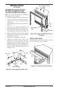
12. Carefully pass wall switch assembly through
rectangular opening from inside mantel (see
Figure 13).
13. Position wall switch assembly vertically over
opening with decal lettering upright. Make
sure wires freely pass through wall without
binding. Align holes in wall plate with 1/8”
pilot holes in mantel wall.
14. Drive mounting screws, removed in step 2 of
Relocating Wall Switch Assembly on pages 10
and 11, through wall plate holes and into pilot
holes in mantel wall.
15. Tighten screws until wall switch assembly
is firmly attached to mantel. Do not over
-
tighten.