


Special offers from our partners!

Find Replacement BBQ Parts for 20,308 Models. Repair your BBQ today.
www.desatech.com
113134-01B
16
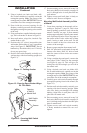
PRESSURE TESTING FIREPLACE GAS
CONNECTIONS
1. Open equipment shutoff valve (see Figure 17,
page 15).
2. Open main gas valve located on or near gas
meter for natural gas or open propane/LP
supply tank valve.
3. Place manual ignition switch in the OFF
position.
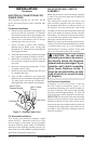
4. Check all joints from equipment shutoff valve
to gas valve (see Figure 18 or 19, page 15).
Apply noncorrosive leak detection fluid to all
joints. Bubbles forming show a leak.
5. Correct all leaks at once.
6. Light fireplace (see Operating Fireplace, page
21). Check all other internal joints for leaks.
7. Turn off fireplace (see To Turn Off Gas to
Appliance, pages 23 or 24).
CONVENTIONAL FIREPLACE
INSTALLATION
Conventional installation of fireplace involves in-
stalling fireplace along with corner, face, or cabinet
mantel with hearth base accessories against a wall
in your home. Follow instructions below to install
fireplace in this manner.
Note: The instructions below show installation us
-
ing the cabinet mantel and hearth base accessories
(see Accessories, page 36). The hearth base acces
-
sory shown is optional for this installation. You
can install fireplace and cabinet mantel directly
on the floor. The corner mantel accessory cannot
be installed with the hearth bases. You must install
corner mantel directly on the floor.
1. Assemble cabinet mantel, hearth base, and
trim accessories. Assembly instructions are
included with each accessory.
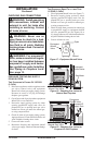
2. When installing blower, install a properly
grounded, 120 volt three-prong electrical out
-
let at fireplace location if an outlet is not there.
If possible, locate outlet so cabinet mantel will
cover it when installed (see Figure 20).
3. If not already completed, install gas piping to
fireplace location. This installation includes an
approved flexible gas line (if allowed by local
codes) after the equipment shutoff valve. The
flexible gas line must be the last item installed
on the gas piping. See Installing Gas Piping
to Fireplace Location,
page 13.
INSTALLATION
Continued
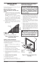
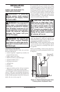
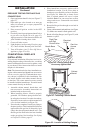
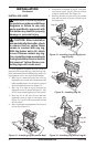
4. Place hearth base accessory against wall at
installation location. Cut an access hole in
hearth top to run flexible gas line to fireplace
(see Figure 20). Make sure to locate access
hole so cabinet mantel will cover it when
installed. Note: You can secure base to floor
using wood screws. Countersink screw heads
and putty over.
5. Route flexible gas line through access hole in
hearth base.
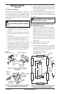
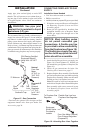
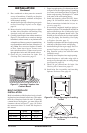
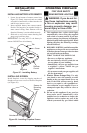
6. Center cabinet mantel on hearth base (see Figure
21). Make sure mantel is flush against wall.
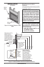
7. Break off nailing flanges (see Figure 22) with
hammer or pliers.
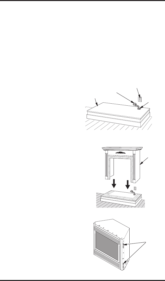
Figure 20 - Placing Hearth Base
Accessory Against Wall
Electrical
Outlet
Hearth Base
Rigid Pipe
and Gas
Shutoff Valve
Gas Line
Access
Hole
Figure 21 - Installing Cabinet Mantel
Cabinet
Mantel
Figure 22 - Location of Nailing Flanges
Nailing
Flanges