


Special offers from our partners!

Find Replacement BBQ Parts for 20,308 Models. Repair your BBQ today.
www.desatech.com
116192-01G6
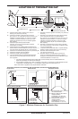
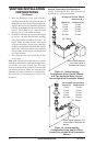
• If recessing into a wall, you can avoid extra
framing by positioning your replace against
an already existing framing member.
• Do not recess termination cap into a wall or
siding.
• You may paint the termination cap with 450º F
(232º C) heat-resistant paint to coordinate with
the exterior nish.
• There must not be any obstruction such as
bushes, garden sheds, fences, decks or util-
ity buildings within 24" from the front of the
termination cap.
• Do not locate termination cap where excessive
snow or ice build up may occur. Be sure to
clear vent termination area after snow falls to
prevent accidental blockage of venting system.
When using snow blowers, do not direct snow
towards vent termination area.
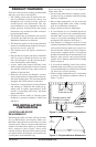
• For horizontal installations above 2,000 feet, it
is recommended that a 12" extension pipe be
added before starter elbow and a round hori-
zontal termination be used (see High Altitude
Installation, page 17).
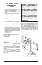
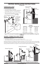
CLEARANCES
Minimum clearances to combustibles for the re-
place are as follows:
*Back and sides 0"
Perpendicular walls 6"
Floor 0"
Ceiling to louver opening 42"
Front 36"
Top of Standoffs 0"
Vent (See venting instructions
for specific venting
clearances.)
Combustible material with a maximum thick-
ness of 5/8" may be ush with the top front of
replace.
* For back and sides of replace, do not pack
with insulation or other materials. 0" clear-
ance to combustible materials are for framing
purpose only.
PRE-INSTALLATION
PREPARATION
Continued
-
-
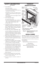
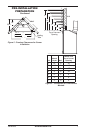
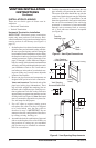
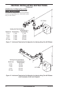
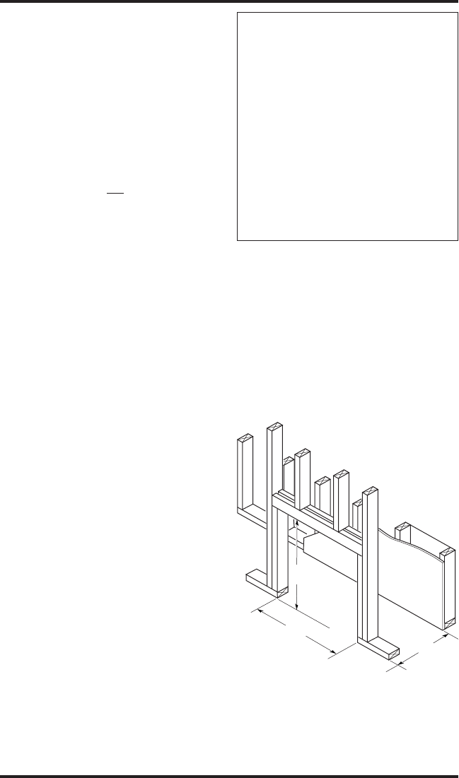
FRAMING AND FINISHING
Figure 4 shows typical framing of this replace.
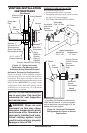
Figure 5, page 7, shows framing for corner instal-
lation. All minimum clearances must be met.
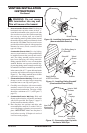
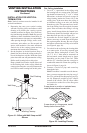
For available accessories for this replace, see
Accessories on page 42. If you are using a separate
combustible mantel piece, refer to Figure 6, page
7, for proper installation height. You can install
noncombustible mantels at any height above the
replace.
Note: Noncombustible mantels may discolor!
Figure 4 - Framing Clearances for
Installation Against an Exterior Wall
36
1
/8"
41
1
/4"
21" Horizontal Vent
24
1
/2" Vertical Vent