Special offers from our partners!

Find Replacement BBQ Parts for 20,308 Models. Repair your BBQ today.

www.desatech.com
116192-01G 17
VENTING INSTALLATION
INSTRUCTIONS
Continued
Note: Install
restrictor into
inner collar of
replace as
shown.
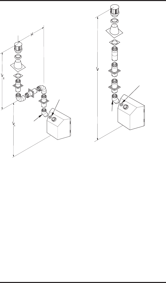
Vertical (V
1
5' min. 6' max.
6' min. 12' max.
7' min. 18' max.
8' min. 20' max.
Note: Vertical (V
1
) + Vertical (V
2
) = 40' max.
Figure 23 - Vertical Venting
Conguration Using Two 90° Elbows
(Vertical Round High Wind Termination
Shown)
45° Elbow
V = 40' max.
Figure 24 - Vertical Venting Conguration
With No Horizontal Run (Vertical Round
High Wind Termination Shown)
Note: Install
restrictor into
inner collar of
replace as
shown.
45° Elbow
HIGH ALTITUDE INSTALLATION
Your DESA direct-vent replace has been tested and
approved for elevations from 0-2000 feet (USA) and
elevations from 0-4500 feet (Canada).
Fireplaces for High Altitude (models ending in
-HA) are for installation above 4000 feet only.
These replaces are equipped with parts specic
for higher altitudes. IMPORTANT: These replac-
es can NOT be converted to Propane/LP gas.
When installing a non-high altitude replace at an
elevation above 2000 feet (in the USA), you may
need to decrease the input rating by changing the
existing burner orice to a smaller size. Reduce
input 4% for each 1000 feet above sea level. Check
with your local gas company for proper orice
size identication.
When installing this replace at an elevation above
4500 feet (in Canada), check with local authorities.
IMPORTANT: For horizontal installations
above 2,000 feet, it is recommended that a 12"
extension pipe be added before starter elbow
(see Figure 25, page 18) and a round horizontal
termination be used.


