


Special offers from our partners!

Find Replacement BBQ Parts for 20,308 Models. Repair your BBQ today.
www.desatech.com
116192-01G 5
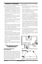
PRODUCT FEATURES
These are a few facts that can help you understand
and enjoy your direct-vent replace:
• The venting system may be routed to the out-
side of your home in several ways. It may vent
through the roof (vertical) or it may vent to an
outside/exterior wall (horizontal). The vent
pipe installation is very important to allow for
proper operation. You must follow the venting
instructions very carefully for either vertical or
horizontal applications.
• This replace may be installed in any room of
your house provided all local codes and these
installation instructions are followed.
• This replace requires a wall switch, hand-held
remote or wall thermostat (millivolt) for opera-
tion (see Accessories, page 42).
• This replace does not require electricity to
operate.
• Only the blower requires electricity if installed
and if you plan to install the blower at a later
date, do not forget to wire the outlet at the bot-
tom of the replace when framing.
• A piezo ignitor and ceramic electrode create
spark to ignite the pilot light. It does not require
any matches, batteries or any other sources of
ignition to light the pilot.
• Each time you turn on your replace, you may
notice some amount of condensation on the in-
side of the replace glass. This is normal and will
disappear after 10-20 minutes of operation.
• Your direct-vent gas replace system (replace
and venting) is a balanced and sealed gas op-
erating unit. It requires approximately 10-20
minutes of operating time before the ame
pattern stabilizes.
• Fireplaces with the sufx of -HA have been
designed to operate at altitudes of 4000 feet
and above.
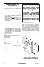
PRE-INSTALLATION
PREPARATION
LOCATION AND SPACE
REQUIREMENTS
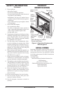
Determine the safest and most efcient location
for your DESA direct-vent replace. Make sure
that rafters and wall studs are not in the way of the
venting system. Choose a location where the heat
output is not affected by drafts, air conditioning
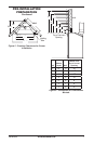
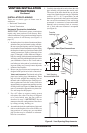
ducts, windows or doors. Figure 2 shows some
common locations. Be aware of all restrictions and
precautions before deciding the exact location for
your replace and termination cap.
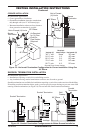
Figure 2 - Common Fireplace Locations
Flush with a wall
Through exterior wall
enclosed in a chase
Corner
installation
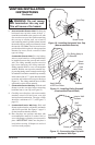
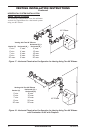
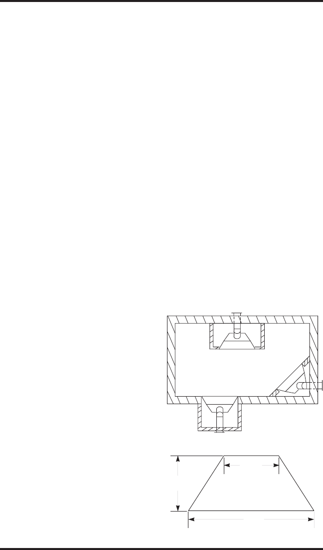
Figure 3 - Fireplace Bottom Dimensions
D
RW
FW
21
1
/8"
41"
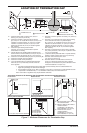
When deciding the location of your replace,
follow these rules:
• Do not connect this replace venting to a chim-
ney ue serving a separate solid-fuel burning
replace or appliance.
• Due to high temperatures, do not locate this
replace in high trafc areas, windy or drafty
areas or near furniture or draperies.
• Proper clearances must be maintained.
• If your replace is to be installed directly on
carpeting, vinyl tile or any combustible mate-
rial other than wood, it must be installed on a
metal or wood panel extending the full width
and depth of the replace. See Figure 3.
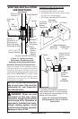
• Your replace is designed to be used in zero
clearance installations. Wall or framing material
can be placed directly against any exterior sur-
face on the back, sides or top of your replace,
except where standoff spacers are integrally
attached. If standoff spacers are attached to your
replace, these spacers can be placed directly
against wall or framing material. See framing
details on page 6.
• If you plan on installing a television or enter-
tainment center recessed above your replace, it
is recommended that you maintain a minimum
18" above top of louver opening.
• When locating termination cap, it is important
to observe the minimum clearances shown in
Figure 7, page 8.
29"