


Special offers from our partners!

Find Replacement BBQ Parts for 20,308 Models. Repair your BBQ today.
www.desatech.com 111244-01C
28
create soot. We recommend that you clean the unit
every three months during operation and have fire-
place inspected yearly by a qualified service person.
We also recommend that you keep the burner tube
and pilot assembly clean and free of dust and dirt.
To clean these parts we recommend using com-
pressed air no greater than 30 PSI. Your local com-
puter store, hardware store, or home center may
carry compressed air in a can. You can use a
vacuum cleaner in the blow position. If using com-
pressed air in a can, please follow the directions
on the can. If you don't follow directions on the
can, you could damage the pilot assembly.
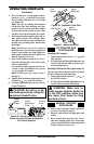
1. Shut off the unit, including the pilot. Allow
the unit to cool for at least thirty minutes.
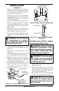
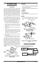
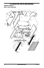
2. Inspect burner, pilot, and primary air inlet
holes on injector holder for dust and dirt (see
Figure 50).
3. Blow air through the ports/slots and holes in
the burner.
4. Check the injector holder located at the end
of the burner tube again. Remove any large
particles of dust, dirt, lint, or pet hair with a
soft cloth or vacuum cleaner nozzle.
5. Blow air into the primary air holes on the in-
jector holder.
6. In case any large clumps of dust have now been
pushed into the burner repeat steps 3 and 4.
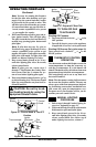
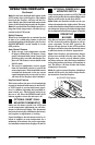
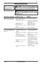
Clean the pilot assembly also. A yellow tip on the
pilot flame indicates dust and dirt in the pilot as-
sembly. There is a small pilot air inlet hole about
two inches from where the pilot flame comes out
of the pilot assembly (see Figures 51 or 52 de-
pending on model). With the unit off, lightly blow
air through the air inlet hole. You may blow
through a drinking straw if compressed air is not
available.
CLEANING AND
MAINTENANCE
Continued
LOG SET
• If you remove one-piece log set for cleaning,
refer to Installing Log Set and Screen, page 21,
for placement instructions.
• Replace log set if broken or chipped (dime-sized
or larger).
CABINET
Air Passageways
• Use a vacuum cleaner or pressurized air to
clean.
Exterior
• Use a soft cloth dampened with a mild soap
and water mixture. Wipe the cabinet to remove
dust.
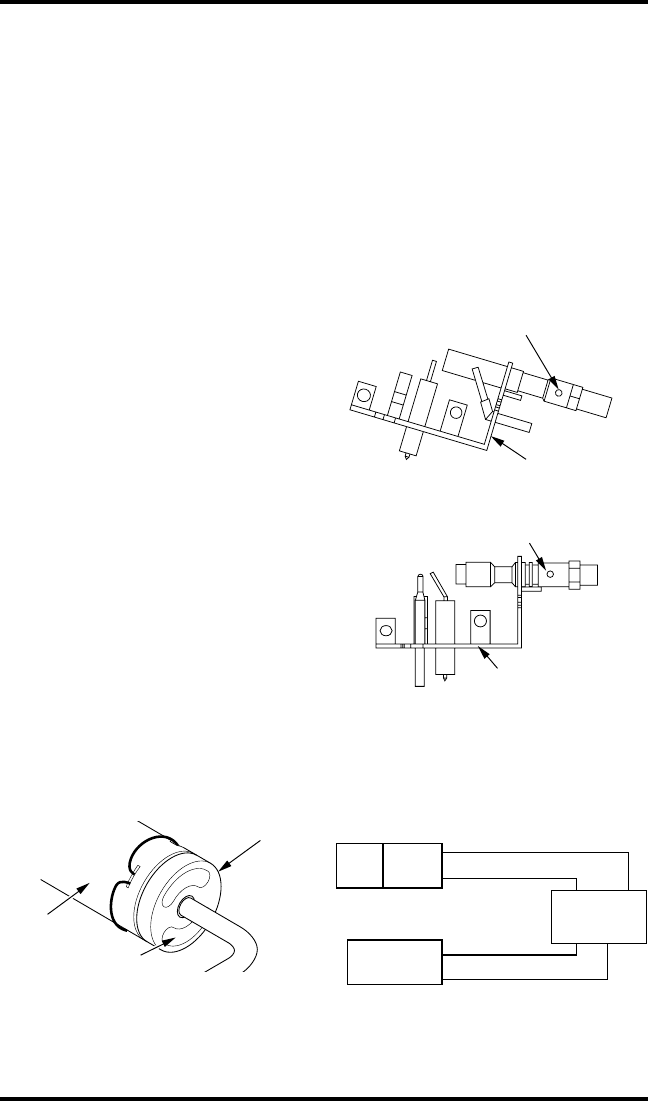
Figure 50 - Injector Holder On Outlet
Burner Tube
Burner
Tube
Injector Holder
Primary Air
Inlet Holes
Figure 51 - Pilot Inlet Air Hole
(Propane/LP Gas)
Pilot Assembly
Pilot Air Inlet Hole
Pilot Assembly
Pilot Air Inlet Hole
Figure 52 - Pilot Inlet Air Hole (Natural
Gas)
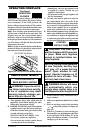
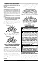
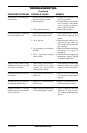
WIRING DIAGRAM
(Remote-Ready Models Only)
Switch
Black
Auto
Off
On
Red
Red
White
Thermopile
Gas Control
TPTH TH
TPTH
TP