


Special offers from our partners!

Find Replacement BBQ Parts for 20,308 Models. Repair your BBQ today.
www.desatech.com
111244-01C
13
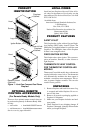
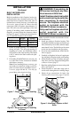
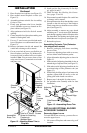
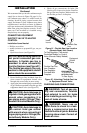
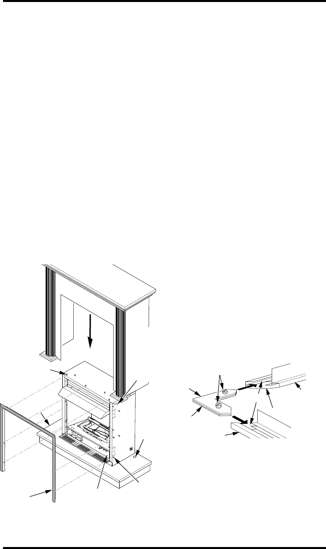
3. Place fireplace on wood base (see Figure 12).
4. Place mantel around fireplace on base (see
Figure 12).
5. Assemble perimeter trim kit. See Assembling
Perimeter Trim.
6. Firmly snap perimeter trim kit on shoulder
screws. Shoulder screws are located on fire-
place cabinet (see Figure 12).
7. Align perimeter trim kit for flush fit around
opening.
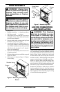
8. Center mantel left to right on base making sure
mantel is flush against wall.
9. Use two 3" wood screws provided and attach
base of fireplace to wooden mantel base (see
Figure 12).
10. Remove perimeter trim kit and mantel. Be
careful not to damage wall or mantel.
11. Cut an access hole in base to run flexible gas
line to fireplace (see Figure 12). Make sure to
locate access hole so mantel will cover it when
installed.
Note:
You can secure base to floor
using wood screws. Countersink screw heads
and putty over.
INSTALLATION
Continued
O
F
F
P
I
L
O
T
O
N
H
I
L
O
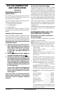
Figure 12 - Attaching Brass Trim to
Fireplace
Shoulder
Screw
Assembled
Brass Trim
Hole for 3" Wood
Screw for Attaching
Fireplace to
Wooden Base
Shoulder
Screws
Gas
Line
Access
Hole
Mantel
Base
Hole for
3" Wood
Screw for
Attaching
Fireplace
to Mantel
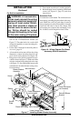
12. Install gas line. See Connecting To Gas Sup-
ply, pages 16 and 17.
13. Check for leaks. See Checking Gas Connec-
tions, pages 17 and 18.
14. Place mantel around fireplace. Be careful not
to damage wall or mantel.
15. Place perimeter trim kit on the shoulder screws
located on the side and top of the fireplace.
Firmly snap trim over shoulder screws on fire-
place (see Figure 12).
16. Adjust assembly to remove any gaps. Attach
remaining two 3" wood screws from hardware
pack through openings inside of fireplace sides
into the mantel. The openings are located at top
behind the area for top louver (see Figure 12).
17. Reinstall top louver.
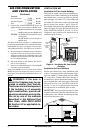
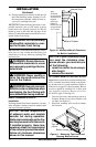
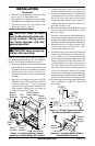
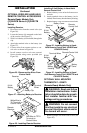
Assembling Perimeter Trim (Perimeter
trim shipped with mantel)
1. Remove packaging from three remaining
pieces of trim.
2. Locate two adjusting plates with set screws,
and two shims in the hardware packet.
3. Align shim under adjusting plate as shown in
Figure 13.
4. Slide one end of adjusting plate/shim in slot on
mitered edge of top brass trim (see Figure 13).
5. Slide other end of adjusting plate/shim in slot
on mitered edge of side perimeter trim (see
Figure 13).
6. While firmly holding edges of perimeter trim
together, tighten both set screws on the ad-
justing plate with slotted screwdriver.
7. Repeat steps 1 through 6 for other corner.
8. Set perimeter trim assembly aside for later
installation.
Figure 13 - Assembling Brass Trim
Side Brass
Trim
Top Brass
Trim
Mitered Edge
Shim
Set Screws
Adjusting
Plate
Slot
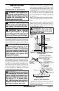
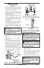
INSTALLING OPTIONAL BLOWER
ACCESSORY GA3450TA
Removing Upper Louver
To install the blower accessory, you must first re-
move the upper louver.
1. Lift screen off fireplace and remove log set if
installed.