


Special offers from our partners!

Find Replacement BBQ Parts for 20,308 Models. Repair your BBQ today.
www.desatech.com 111244-01C
14
INSTALLATION
Continued
3
2
1
O
F
F
P
I
L
O
T
O
N
H
I
L
O
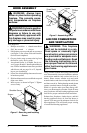
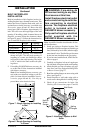
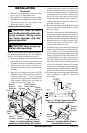
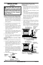
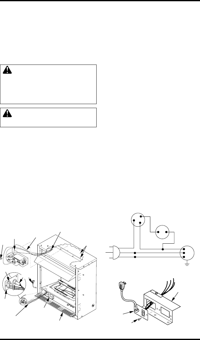
Figure 14 - Installing Blower Bracket
Assembly (Remote-Ready Unit Shown)
Wire
Harness
Blower
Bracket
Assembly
Screw
Wire
Harness
Switch
Wiring Routing
Hole in Baffle
Switch
Plate
Remote/
Blower
Bracket
Power
Cord
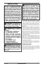
Lower Louver Door
Blower
Mounting
Holes
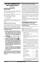
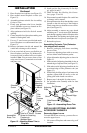
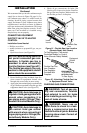
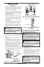
Figure 16 - Installing Switch Plate to
Remote/Blower Bracket
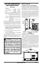
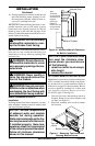
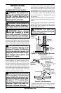
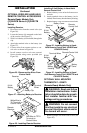
Figure 15 - Wiring Diagram For Blower
Accessory Standard Installation
Red
Red
Fan Switch
(Auto/Off/On)
Blue
Blue
Thermostat
Switch
(N.O.)
Green
White
Green
White
On
110/115
V.A.C.
Blower
Motor
Black
Off
1
2
3
Auto
Remote/
Blower
Bracket
Switch
Plate
Screw
2. Remove 4 screws from upper louver (see Fig-
ure 11, page 12). Save these screws.
3.
Pull upper louver straight out from the cabinet.
Be careful not to scratch the paint. Set louver aside.
4. Open lower louver door by swinging door
down (see Figure 11, page 12).
Installing Blower Accessory
CAUTION: Label all wires
prior to disconnection when ser-
vicing controls. Wiring errors
can cause improper and dan-
gerous operation.
CAUTION: Verify proper op-
eration after servicing.
Note:
If you are using a mantel with your fireplace,
use the following instructions. If your fireplace is
built-in, see For Built-In Installation, page 15.
1. Install snap bushings found in blower kit into
hole in left side of outer casing and into one
of the holes in rear of remote/blower bracket.
2. Make sure the wire harness is firmly con-
nected to the terminals on the blower bracket
assembly.
3. Note the wire locations on back of AUTO/
OFF/ON switch. The terminals on back of
switch are numbered 1, 2, and 3. Carefully
remove red wire from terminal 3 and blue wire
from terminal 1. Black wire can remain on
middle terminal 2 (see Figure 14).
4. Carefully disconnect green and white wires
at their insulated connectors (see Figure 15).
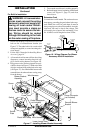
5. In top of the fireplace cabinet, locate the four
mounting holes on the outer casing. Align
these four holes with those on the blower
bracket assembly. Attach blower bracket as-
sembly to the outer casing with 4 #10 screws
provided (see Figure 14).
6. Route the wire harness through the hole in left
side of baffle and between firebox wrapper
and outer casing.
7. Insert the 4 wire harnesses from behind the re-
mote/blower bracket through hole in rear of
bracket with bushing and through the left rect-
angular hole to front of fireplace (see Figure 14).
8. Reconnect red wire to switch position 3. Re-
connect blue wire to switch position 1. Re-
connect green and white wires.
9. Install the switch plate on the remote/blower
bracket with 2 #10 screws provided (see Fig-
ure 16). Route power cord out of the cabinet
by inserting it through the bushing on the outer
casing (see Figure 14). Plug fan kit into 120-
Volt grounded power supply and test opera-
tion. Note: When switch is in the AUTO posi-
tion, the fan will start after the fireplace has
run for a few moments. The fan will continue
to run for several moments after the fireplace
has been turned off. When switch is in the ON
position, the fan will run until turned to OFF.
10. Reinstall upper louver beginning with bottom
screws (see Figure 11, page 12). Close lower
louver door.