


Special offers from our partners!

Find Replacement BBQ Parts for 20,308 Models. Repair your BBQ today.
www.desatech.com
115043-01C
8
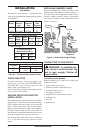
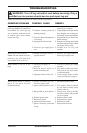
Test Pressures Equal To or Less Than
1/2 PSIG (3.5 kPa)
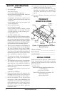
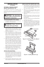
1. Close equipment shutoff valve (see Figure 5).
2. Pressurize supply piping system by either us
-
ing compressed air or opening main gas valve
located on or near gas meter.
3. Check all joints from gas meter to equipment
shutoff valve (see Figure 5). Apply noncorro
-
sive leak detection fluid to gas joints. Bubbles
forming show a leak.
4. Correct all leaks at once.
INSTALLATION
Continued
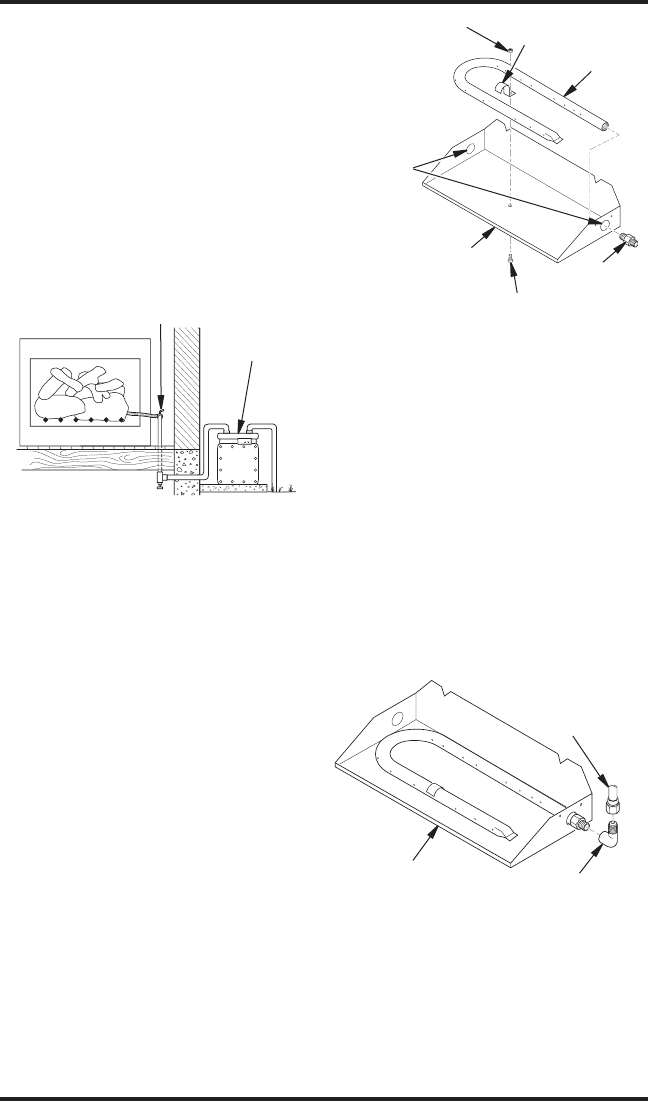
Figure 5 - Checking Gas Joints
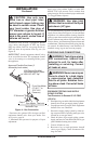
HEARTH KIT ASSEMBLY AND
INSTALLATION
1. Determine which side the gas line will be coming
into the fireplace.
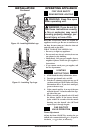
2. Using a hammer and screw driver, remove
knockout plug from the side of the pan that
corresponds to the gas line (see Figure 6).
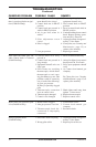
3. Unscrew burner inlet fitting from burner
manifold.
4. Place burner manifold in pan with threaded
opening facing open knockout plug.
5. Using thread sealant (resistant to the action
of propane/LP gas) on larger end of fitting,
screw the burner inlet fitting through hole and
into burner manifold (see Figure 6). Tighten
using a wrench.
6. Using burner clamp, screw, and nut provided,
assemble clamp to pan (“U” style and triple
burners only). This will hold the burner mani
-
fold in place.
7. If using optional GA9050A kit, go to Optional
GA9050A On/Off Safety Valve/Pilot Kit section
for installation instructions. If using optional
GA9150A kit, follow instructions included
with kit for installation and operation.
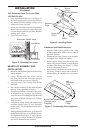
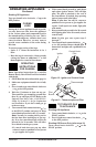
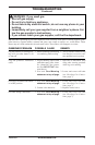
Figure 7 - Connecting Gas to Appliance
Adapter
Fitting
Gas
Connector
Tube
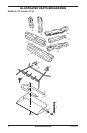
Burner Pan Assembly
(Facing Front of
Fireplace)
Figure 6 - Installing Burner
Burner Inlet
Fitting
Screw
Nut
Burner
Clamp
Burner Pan
(Front)
Burner Manifold
Knockout
Plugs
Installation and Gas Connection
1. Place the burner pan assembly in the center
of the fireplace floor. Make sure the front of
pan faces forward.
2. Thread the gas supply fitting to the fireplace
gas supply pipe. Use thread sealant.
3. Install adapter fitting onto the burner inlet
fitting using thread sealant on male threads
of burner inlet fitting (see Figure 7). Adjust
to most convenient position.
4. Install the gas connector tube to the gas sup
-
ply fitting. Carefully shape tube to attach to
adapter fitting. Be careful not to cause kinks
in tube.
Gas Meter
Equipment Shutoff Valve