


Special offers from our partners!

Find Replacement BBQ Parts for 20,308 Models. Repair your BBQ today.
www.desatech.com
115043-01C 7
CAUTION: Use only new,
black iron or steel pipe. Inter-
nally-tinned copper tubing may
be used in certain areas. Check
your local codes. Use pipe of
1/2" diameter or greater to allow
proper gas volume to log set. If
pipe is too small, undue loss of
volume will occur.
Installation must include a equipment shutoff
valve, union, and plugged 1/8" NPT tap. Locate
NPT tap within reach for test gauge hook up.
NPT tap must be upstream from log set (see
Figure 4).
IMPORTANT: Install equipment shutoff valve
in an accessible location. The equipment shutoff
valve is for turning on or shutting off the gas to
the appliance.
INSTALLATION
Continued
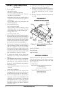
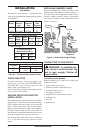
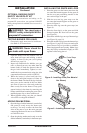
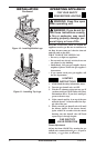
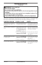
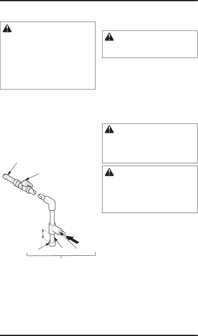
Figure 4 - Gas Connection
* Purchase the optional CSA design-certified
equipment shutoff valve from your dealer. See
Accessories, page 18.
** Minimum inlet pressure for purpose of input
adjustment.
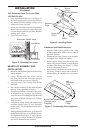
Apply pipe joint sealant lightly to male NPT
threads. This will prevent excess sealant from
going into pipe. Excess sealant in pipe could result
in a clogged burner injector.
WARNING: Use pipe joint
sealant that is resistant to liquid
petroleum (LP) gas.
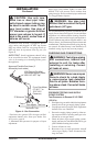
We recommend that you install a sediment trap in
supply line as shown in Figure 4. Locate sediment
trap where it is within reach for cleaning. Install in
piping system between fuel supply and appliance.
Locate sediment trap where trapped matter is not
likely to freeze. A sediment trap traps moisture and
contaminants. This keeps them from going into log
set controls. If sediment trap is not installed or is
installed wrong, log set may not run properly.
CHECKING GAS CONNECTIONS
WARNING: Test all gas piping
and connections, internal and
external to unit, for leaks after
installing or servicing. Correct
all leaks at once.
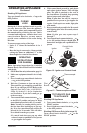
WARNING: Never use an open
flame to check for a leak. Apply
a noncorrosive leak detection
fluid to all joints. Bubbles form
-
ing show a leak. Correct all leaks
at once.
PRESSURE TESTING GAS SUPPLY
PIPING SYSTEM
Test Pressures In Excess Of 1/2 PSIG
(3.5 kPa)
1. Disconnect log set and its individual equipment
shutoff valve from gas supply piping system.
2. Cap off open end of gas pipe where equipment
shutoff valve was connected.
3. Pressurize supply piping system by either us
-
ing compressed air or opening main gas valve
located on or near gas meter.
4. Check all joints of gas supply piping system.
Apply noncorrosive leak detection fluid to gas
joints. Bubbles forming show a leak.
5. Correct all leaks at once.
6. Reconnect log set and equipment shutoff
valve to gas supply. Check reconnected fit
-
tings for leaks.
3" Minimum
Sediment Trap
From Gas Meter
(5" W.C.** to
10.5" W.C.
Pressure)
CSA Design-Certified
Equipment Shutoff Valve
With 1/8" NPT Tap*
Approved Flexible Gas Hose (if
allowed by local codes)
Tee Joint
Pipe Nipple
Cap