


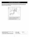
Special offers from our partners!

Find Replacement BBQ Parts for 20,308 Models. Repair your BBQ today.
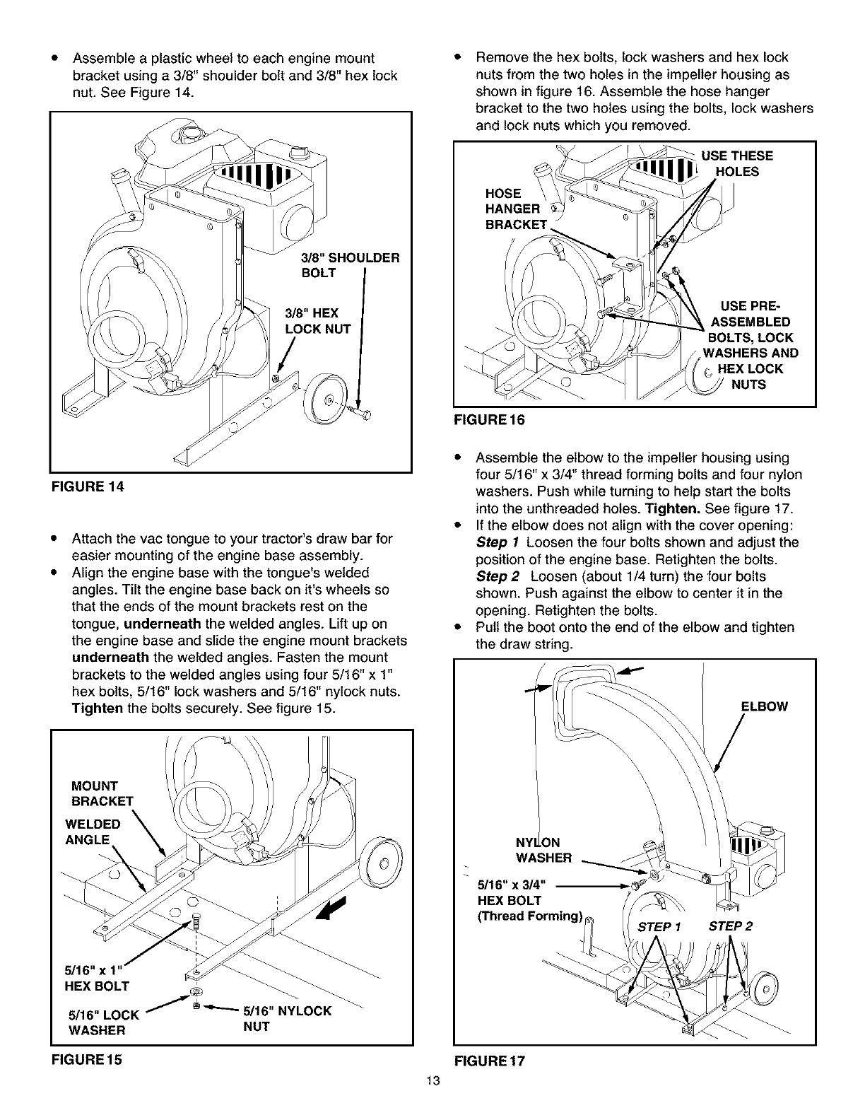
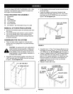
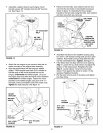
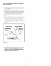
• Assemble a plastic wheel to each engine mount
bracket using a 3/8" shoulder bolt and 3/8" hex lock
nut. See Figure 14.
3/8"SHOULDER
FIGURE 14
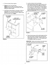
Attach the vac tongue to your tractor's draw bar for
easier mounting of the engine base assembly.
Align the engine base with the tongue's welded
angles. Tilt the engine base back on it's wheels so
that the ends of the mount brackets rest on the
tongue, underneath the welded angles. Lift up on
the engine base and slide the engine mount brackets
underneath the welded angles. Fasten the mount
brackets to the welded angles using four 5/16" x 1"
hex bolts, 5/16" lock washers and 5/16" nylock nuts.
Tighten the bolts securely. See figure 15.
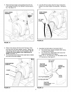
MOUNT
BRACKET
WELDED
ANGLE
5/16" x 1= _
HEX BOLT _
5/16" LOCK _ _'-'-'- 5/16" NYLOCK
WASHER NUT
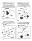
Remove the hex bolts, lock washers and hex lock
nuts from the two holes in the impeller housing as
shown in figure 16. Assemble the hose hanger
bracket to the two holes using the bolts, lock washers
and lock nuts which you removed.
USE THESE
HOLES
HOSE
HANGER
FIGURE16
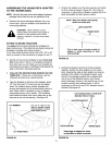
USE PRE-
ASSEMBLED
LOCK
fWASHERS AND
G HEX LOCK
NUTS
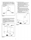
Assemble the elbow to the impeller housing using
four 5/16" x 3/4" thread forming bolts and four nylon
washers. Push while turning to help start the bolts
into the unthreaded holes. Tighten. See figure 17.
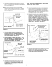
• If the elbow does not align with the cover opening:
Step I Loosen the four bolts shown and adjust the
position of the engine base. Retighten the bolts.
Step2 Loosen (about 1/4 turn) the four bolts
shown. Push against the elbow to center it in the
opening. Retighten the bolts.
• Pull the boot onto the end of the elbow and tighten
the draw string.
ELBOW
WASHER
5/16" x 3/4"
HEXBOLT
(Thread Forming_._
STEP 1
STEP 2
FIGURE 15 FIGURE 17
13