


Special offers from our partners!

Find Replacement BBQ Parts for 20,308 Models. Repair your BBQ today.

19
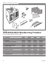
SHR Series Woodburning Fireplaces
20001384
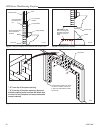
removed from gas line tube to repack space around the
pipe. Material should be inserted from outside of the
fireplace and packed tightly to totally seal between the
pipe and tube.
NOTE: Gas pipe should not come in contact with any
wood structures until it has reached a point at least
one (1) inch away from fireplace side.
NOTE: When installing an ANSI Z21.11.2 ventless appli-
ance, the finishing material used for the mantel must be
rated at 250°F or greater.
BTU input of a gas appliance installed in fireplace should
be rated less than 100,000 BTU/Hr.
Gas pipe installation is intended for connection to a deco-
rative gas appliance only when (1.) incorporating an auto-
matic shutoff device and (2.) complying with the Standard
for Decorative Gas Appliances for Installation in Vented
Fireplaces (ANSI Z21.60) or CSA draft requirements
for Gas-Fired Log Lighters for Woodburning Fireplaces
(Draft No. 4, August 1993).
Decorative gas appliance should be installed in accor-
dance with the National Fuel Gas Code, ANSI Z223.1/
NFPA 54 (latest edition).
CAUTION: WHEN USING DECORATIVE GAS
APPLIANCE, FLUE DAMPER MUST BE SET
IN FULLY OPEN POSITION. IF YOU HAVE
GLASS DOORS ON THE FIREPLACE, THEY
MUST ALSO BE FULLY OPENED.
WARNING: DO NOT OPERATE AN
UNVENTED GAS LOG SET IN THIS FIRE-
PLACE WITH THE CHIMNEY REMOVED.
WARNING: WHEN INSTALLING AN
UNVENTED GAS LOG SET, THE
CFM
CORPORATION MODEL AH3244BK OR
AH3244PB 4" ADJUSTABLE HOOD MUST BE
USED.
Installing Line for Gas Logs
CFM Corporation fireplaces are designed to accept a 1/2
inch gas line for installation of an approved gas appli-
ance. (CFM Corporation manufactures a wide variety of
gas logs for use in CFM Corporation fireplaces.)
Be sure to have the appliance installed in accordance
with building codes.
Gas connection may enter from either left or right side of
the fireplace.
Locate appropriate gas line in the outer casing of fire
-
place and remove insulation from gas line tube. (Fig. 36)
From inside the fireplace, locate the knockout on the fire
-
brick -- be sure you are on the appropriate or "gas line"
side of the fireplace. Using a flat bladed screwdriver or
small chisel and hammer, carefully tap around the knock-
out until it loosens and falls out.
Install 1/2 inch certified gas pipe through opening. After
gas pipe installation is complete, use insulation that was
FP1171
sealing detail
12/20/01 djt
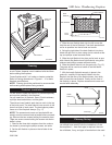
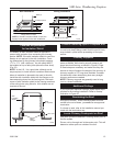
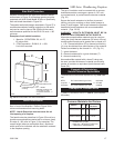
Wall Covering
2 x 4 Header
- Do Not Notch at
Ledge Brackets
Fig. 22 or 23
Hearth Extension
Hearth
Extension Insulation
Molding used to
Fasten Hearth
Extension
in Place
Majestic Safety Strips Must
be Overlapped 1/2" Min.
Seal Crack Between
Fireplace and Hearth
Extension with
Noncombustible Material
FP1171
Fig. 34 Sealing detail.
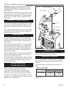
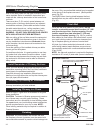
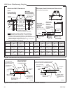
FP1172
sealing detail 2
12/20/01 djt
2 x 4 Header
- Do Not Notch at
Ledge Brackets
Fig. 24
Wall Covering
Noncombustible
Decorative Facing
Seal All Cracks
Between Fireplace
Surround and Wall
Materials with
Noncombustible
Material
Noncombustible
Decorative Covering
Majestic Safety Strips Must
be Overlapped 1/2" Min.
Seal Crack Between Fire-
place and Hearth Exten-
sion with Noncombustible
Material
FP1172
Fig. 35 Sealing detail.
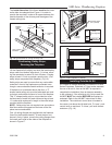
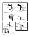
Hearth
Extension
1"
Min.
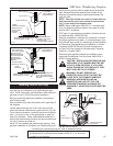
FP560SHR
SHR series
5/12/99 djt
1/2"
FP560SHR
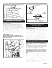
Fig. 36 Gas line access.
Hole in Outer Casing
Gas Line
Tubing
Ceramic
Knockout
Hole in
Outer Casing
Supply Line
Repack Insulation
Ceramic Knockout
(both sides)
Only unvented gas log sets which have been found to comply with
the Standard for Unvented Room Heaters, ANSI Z21.11.2, are to be
installed in this fireplace.
If installing an unvented gas log set, refer to statement below: