


Special offers from our partners!

Find Replacement BBQ Parts for 20,308 Models. Repair your BBQ today.

11
SHR Series Woodburning Fireplaces
20001384
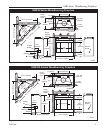
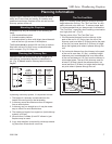
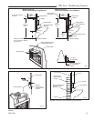
The inside dimension of the frame must be the same
as the hole size selected from Figure 11 in order to
provide the required 2 inches of air space between the
outside diameter of the chimney and the edges of the
framed ceiling hole.
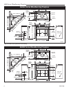
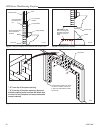
Positioning, Safety Strips,
Securing the Fireplace
Slide fireplace into position.
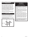
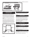
Lift the fireplace front slightly and slide the metal safety
strips under front bottom edge about 1¹⁄₂ inches, allow-
ing the remainder to extend in front of firebox. Overlap
strips at least 1/2 inch to provide a positive joint. (Flat
safety strips are packed with fireplace.) (Fig. 16)
Safety strips are used to ensure that any combustible
materials in front of the fireplace are protected even
though a noncombustible hearth extension is required.
If fireplace is to be elevated above the floor, a “Z”
shaped metal safety strip must be fabricated and used
to protect combustible surfaces in front of the fireplace.
This “Z” shaped safety strip is not provided but must
be fabricated of metal with each horizontal leg at least
1¹⁄₂ inches wide and equal in length to the metal strips
provided with the fireplace.
NOTE: Safety strips are not required over noncombus-
tible floors where all supports at the base of the fire-
place are noncombustible.
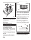
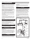
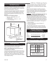
Four (4) nailing flanges are supplied with the fireplace
(found on the fireplace hearth). To level the box and
secure it firmly in place, remove the nailing flanges from
the hearth and install at the sides of the fireplace as
shown in Figure 17.
FP557a
SHR
5/11/99 djt
"
FP557a
Fig. 16 Safety strip installation.
Metal Safety Strips
(1, 2 or 3 pieces)
"Z" Safety
Strip
(not supplied)
Hearth Ext.
Plat-
form
Fire-
place
1/2" Min.
Overlap
FP549
9/29/97
BR/BC
FP549
Fig. 17 Fasten fireplace in position.
Nail Side-
nailing
Flanges
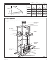
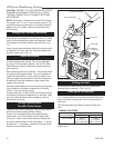
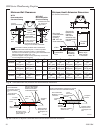
Installing Outside Air Kit
An outside air damper assembly is installed in all SHR
Series Fireplaces. If desired, or if local codes mandate
the use of an air kit, then an AK-MST is required to
complete the installation (from air damper assembly
to the outdoors). If the outside air kit is to be used, the
AK-MST MUST be installed BEFORE the fireplace is
enclosed. Refer to the AK-MST instructions for field
installation. The outside air control lever is located in
the center, just above the left side brick. To 'open', push
control lever up and back. To 'close', pull lever forward
and down. (Fig. 18)
FP551b
SHR
5/11/99 djt
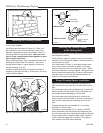
New Framing
Members
Existing
Ceiling
Joists
Chimney
Hole
17¹⁄₂"
(445 mm)
FP551b
Fig. 15 Typical frame for ceiling chimney hole
17¹⁄₂"
(445 mm)