


Special offers from our partners!

Find Replacement BBQ Parts for 20,308 Models. Repair your BBQ today.
14
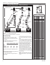
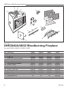
SHR Series Woodburning Fireplace
20001384
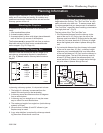
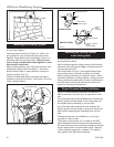
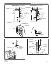
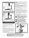
Cut and Frame Roof Hole
Size of roof hole varies with the type of chimney termi-
nation installed. Refer to installation instructions pro-
vided with the chimney termination to find correct size
roof hole.
There must be a 2" (51 mm) air space between out-
ermost portion of chimney sections and any adjacent
combustible surfaces. (Combustible surfaces include
burnable materials such as: ceiling members, joists,
flooring, combustible insulation and roof structures.)
WARNING: DO NOT PACK REQUIRED AIR SPACES
WITH INSULATION OR OTHER MATERIALS.
Mark an outline of the roof hole around the centerpoint
of the nail. NOTE: Hole dimensions given in the chim-
ney top installation instructions are horizontal dimen-
sions; therefore, the hole size must be marked on the
roof accordingly.
Cover the opening of the installed chimney so debris
cannot get into the system.
Cut and frame the hole. It is good practice to use fram-
ing lumber that is the same size as the rafters. Install
the frame securely because the chimney top and flash-
ing anchored to the frame must be able to withstand
heavy winds.
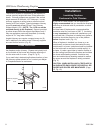
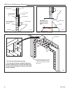
Install Remainder of Chimney Sections
Since you have already preplanned the height of your
termination according to the Ten Foot Rule, continue to
install pipe to the predetermined height.
Check the chimney top installation instructions for
details on how high above the roof top the chimney sec-
tions (all pipes) should extend.
Installing Top Housing or Termination
Follow the installation instructions provided with the
chimney termination you have selected.
Installing Chimney in a Chase
Refer to Page 5, Figure 4 for an illustration of a typical
chase installation.
CAUTION: Treatment of firestop spacers and construc-
tion of chase may vary with type of building. These
instructions are not a substitute for local building codes.
You must check your local building codes to determine
specific requirements for your city or state. NOTE:
Other building materials may be required in addition to
Firestop Spacers.
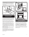
Finishing
CAUTION: All joints between the finished wall and
the fireplace surround (top/sides) must be sealed with
noncombustible material to prevent cold air leakage into
FP559SHR
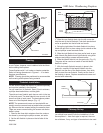
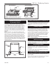
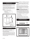
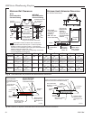
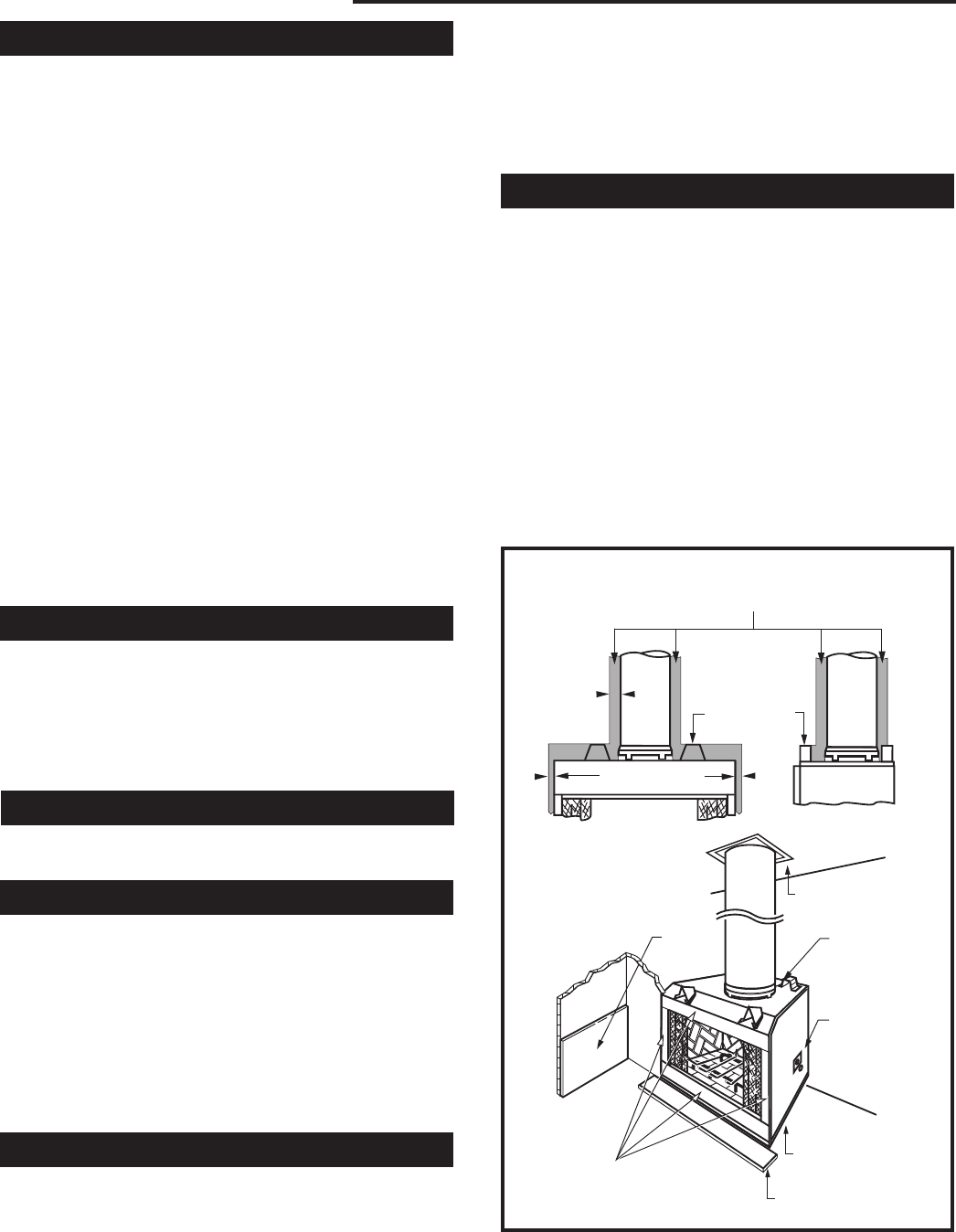
Fig. 23 Minimum clearances to combustibles.
FP559SHR
SHR air spaces
5/12/99 djt
Air Space Clearances
Combustible framing material MUST NOT pen-
etrate AIR SPACE (shaded areas)
Standoff
2"
³⁄₄" Air Space
to Sides
Firestop
Front View
Side View
Wall
Shield
3/4" Air Space
to Back
3/4" Air Space
to Sides
0" Clearance to Floor
Hearth Extension
Only noncombustible material
may be applied as facing to
the black fireplace surround.
the room. Only noncombustible material may be applied
to the facing of the fireplace surround. (Black painted
area) (Fig. 23)
The SHR52 has a framing shield between the front
standoffs that may be used to attach finish material.
(Fig. 25)
Finish Wall
Finish the wall with material of your choice. Do not
install a combustible mantel shelf less than 12" (305
mm) from the top of the fireplace opening. Do not
install a mantel face plate less than 6" (159 mm)
from top of fireplace opening. (Fig. 29) If a combus-
tible material is used below a flat mantel shelf, consult
your local building codes for minimum clearance from
top of fireplace opening to bottom of mantel shelf.
All joints (top, bottom and sides) where wall or deco-
rative facing material meets fireplace surround must
be completely sealed with a noncombustible material.
(Figs. 24-29)
NOTE: No side wall protection is required for fireplaces
installed at 45° to two (2) side walls (corner installation).