


Special offers from our partners!

Find Replacement BBQ Parts for 20,308 Models. Repair your BBQ today.

17
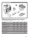
SHR Series Woodburning Fireplaces
20001384
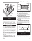
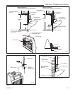
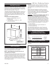
Side Wall Protection
Adjacent combustible side walls that are within dimen-
sions shown in Figure 30 of fireplace opening must be
protected with Wall Shield Model SP40 or a specifically
built wall shield described in Figure 29.
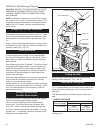
The special wall shield design described in Figure 27 is
an alternate method of adding protection to side walls
and can be used in place of the SP40 with the same
wall clearances specified for the SP40. Rt must =1.85
minimum.
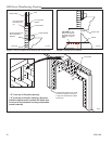
Examples of wall shield insulation:
1. Manville - CERAFORM 126, K=.27,
1/2 inches thick
2. CFM Corporation - EH2416, K = .458,
1 inch thick required.
FP838
Wall shield
5/25/99 djt
40"
Min.
40" Min.
Decorative Non-
combustible Rigid
Covering
Noncombustible Insula-
tion
RT = 1.85 Min.
(Manville Ceraform 126
- 1/2" Thick or CFM
Corporation EH2416 - 1"
Thick)
Fig. 30 Noncombustible wall shield dimensions.
FP838
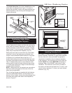
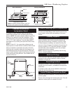
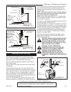
The top of insulation must be covered with a noncom-
bustible decorative covering or a piece of .018” mini-
mum sheet metal, to protect hearth extension material.
(Fig. 32)
Secure the hearth extension to the floor to prevent
shifting, using trim molding or other similar means at
three (3) outer edges. Seal crack between the fireplace
hearth and hearth extension with a noncombustible
material. (Figs. 32-35)
WARNING: HEARTH EXTENSION MUST BE IN
-
STALLED IN ACCORDANCE WITH FIGURE 26.
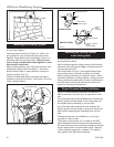
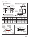
Alternate noncombustible materials may be used pro-
viding the (total) thermal resistance (Rt value) of the al-
ternate material employed is greater than or equal to R
= 1.09. Thermal resistance (R) or thermal conductivity
(K), may be obtained from manufacturer of the material.
Factors are related by the formula K = 1/R. (Fig. 31)
T = given thickness
R = thermal resistance for a given thickness (T)
K = thermal conductivity
Noncombustible material with a lower R value may
be used, provided thickness of material is sufficiently
greater to maintain an equivalent (total) thermal resis-
tance (Rt).
Example of Determining
Hearth Extension Equivalents
To determine the thickness required for any new mate-
rial:
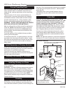
Hearth Installation
A hearth extension is required to protect a combustible
floor in front of the fireplace. Refer to Figure 30 for
minimum dimensions and mounting detail.
NOTE: Hearth Extension must not cover the air
inlet opening of a fireplace.
The hearth extension described in Figure 32 must be a
durable noncombustible material with a minimum (total)
Rt value of 1.09; refer to Figure 31 for examples. The
overall height (above a combustible floor), depth and
width must be as indicated, with the extension centered
to the fireplace opening.
FP533ADD
Fig. 31 Hearth extension material factors.
Common Materials And Factors
Material K*
R
Minimum
Thickness
EH2416
Common Brick
0.458
5.0
1.09 0.50 in.**
0.10 5.46 in.**
R Value is for inch.
* Units of K = BTU/SQ FT/HR/˚F/IN
** Thickness of Listed Material
FP533ADD
Addendum
6/1/99 djt
8/4/99 changed .2 to .1
one inch to 1/2 inch djt
Example for Common Brick
T (new) = 5.0/0.458 x 0.50 in. = 5.46 in. (new required
thickness).
NEW K of new material (per inch) thickness
required = X of listed
thickness K of listed material (per inch) material